
Installation Guide

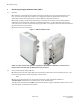
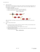
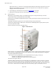
Table Of Contents
- Purpose & Applicability of This Guide
- Special Considerations and Safety Warnings
- Table of Contents
- 1. Introducing Intelligent Backhaul Radio (“IBR”)
- 2. Getting Started
- 3. Communicating with IBR
- 4. Preconfiguring IBRs
- 4.1.1 Web Graphical User Interface (GUI) – User names and passwords for the GUI are managed independently from CLI user names and passwords. For additional information, see the GUI section of the CLI Guide.
- 5. Installing IBR
- 5.3.1 Mounting Location - Choosing the best possible mounting location for IBR is important for safety, security, and link performance.
- 5.3.2 Fastback Networks’ Articulating Bracket - Fastback Networks offers an articulating mount that can be mounted on walls or masts and adjusted up to + 45 degrees in elevation and azimuth in 15 degree increments. The figure below shows the mountin...
- 6. Features & Functionality
- 7. Field Test Procedure
- Federal Communications Commission (FCC) Compliance Statement
IBR Installation Guide
Page 9 of 21 Doc # 770-00033.0
Jan. 22, 2016
offset cable losses; e.g., cable loss in a one hundred meter Ethernet cable between the power source and
IBR will be approximately five (5) watts, in which case the power source would need to be capable of
supplying at least forty-six (46) watts.
d. A grounding lug as described in the section titled Installing IBR in this Guide.
e. Appropriate mounting hardware for the PoE injector(s) if one will be used.
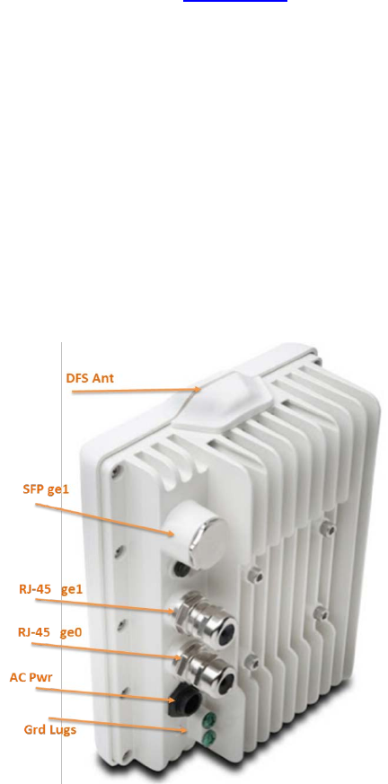
2.3 External Features
IBR includes a 3-port Ethernet switch. Two Gigabit Ethernet ports are exposed externally, and one is
connected internally to the RF link between a pair of IBRs.
External ports are identified as Gigabit Ethernet ports 0 and 1 (ge0 and ge1) and are located as shown in the
illustration below.
The RF port is identified as ge3 and is not accessible externally except via the RF link.
A fourth port, designated ge2, is dedicated to radar detection and DFS (Dynamic Frequency Selection) and
cannot be used for data traffic.
External connectors are shown in the figure below.
Figure 4 - IBR Connectors
Radio parameters are configured through the radio 0 (rad0) interface, while switching parameters that apply
both to the physical Gigabit Ethernet ports and the radio port, such as VLAN, QoS, and CoS, are configured
through the Gigabit Ethernet interface.
Note: Earlier versions of IBR had three external Gigabit Ethernet ports (ge0, ge1, and ge2):
- IBR-10xx series IBRs had three RJ-45 connectors, and
- IBR-12xx series IBRs had one RJ-45 connector and two SFP ports.
The connector for ge0 is an RJ-45.
The factory-default connector for ge1 is an RJ-45 and ge1 is configured for a copper connection. A separate
fixture can be fitted with an SFP connector using Fastback Networks’ SFP Accessory Kit. The ge1 RJ-45 and
SFP connectors can be installed at the same time and either one can be used; however, they can be used only
one at a time. The operator must configure ge1 for either the RJ-45 (copper) or SFP (fiber) connector.