
Installation Guide

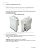
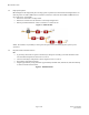
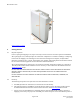
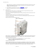
Table Of Contents
- Purpose & Applicability of This Guide
- Special Considerations and Safety Warnings
- Table of Contents
- 1. Introducing Intelligent Backhaul Radio (“IBR”)
- 2. Getting Started
- 3. Communicating with IBR
- 4. Preconfiguring IBRs
- 4.1.1 Web Graphical User Interface (GUI) – User names and passwords for the GUI are managed independently from CLI user names and passwords. For additional information, see the GUI section of the CLI Guide.
- 5. Installing IBR
- 5.3.1 Mounting Location - Choosing the best possible mounting location for IBR is important for safety, security, and link performance.
- 5.3.2 Fastback Networks’ Articulating Bracket - Fastback Networks offers an articulating mount that can be mounted on walls or masts and adjusted up to + 45 degrees in elevation and azimuth in 15 degree increments. The figure below shows the mountin...
- 6. Features & Functionality
- 7. Field Test Procedure
- Federal Communications Commission (FCC) Compliance Statement
IBR Installation Guide
Page 5 of 21 Doc # 770-00033.0
Jan. 22, 2016
Figure 3 - IBR Dimensions .................................................................................................................................................................................................7
Figure 4 - IBR Connectors ..................................................................................................................................................................................................9
Figure 5 – AC Power Connector ................................................................................................................................................................................... 10
Figure 6 – Available AC Power Cable ........................................................................................................................................................................ 10
Figure 7 – IBR-1301 External Connectors .............................................................................................................................................................. 12
Figure 8 – Ground Lug ...................................................................................................................................................................................................... 15
Figure 9 - IBR with Mounting Bracket ...................................................................................................................................................................... 16
Figure 10 – IBR Mounted on Pole ............................................................................................................................................................................... 16
Figure 11 – RJ-45 Plug Assembly ................................................................................................................................................................................ 17
Figure 12 – Surge Suppressors ..................................................................................................................................................................................... 19