
Installation Guide
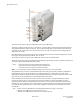
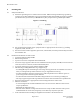
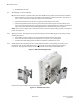
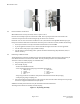
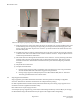
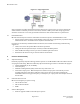
Table Of Contents
- Purpose & Applicability of This Guide
- Special Considerations and Safety Warnings
- Table of Contents
- 1. Introducing Intelligent Backhaul Radio (“IBR”)
- 2. Getting Started
- 3. Communicating with IBR
- 4. Preconfiguring IBRs
- 4.1.1 Web Graphical User Interface (GUI) – User names and passwords for the GUI are managed independently from CLI user names and passwords. For additional information, see the GUI section of the CLI Guide.
- 5. Installing IBR
- 5.3.1 Mounting Location - Choosing the best possible mounting location for IBR is important for safety, security, and link performance.
- 5.3.2 Fastback Networks’ Articulating Bracket - Fastback Networks offers an articulating mount that can be mounted on walls or masts and adjusted up to + 45 degrees in elevation and azimuth in 15 degree increments. The figure below shows the mountin...
- 6. Features & Functionality
- 7. Field Test Procedure
- Federal Communications Commission (FCC) Compliance Statement
IBR Installation Guide
Page 13 of 21 Doc # 770-00033.0
Jan. 22, 2016
The connector for ge0 is an RJ-45 (configured for PoE
+
only on IBR-1300).
The factory-configured connector for ge1 is an RJ-45. A separate fixture can be fitted with an SFP connector
using Fastback Networks’ SFP Accessory Kit. The ge1 RJ-45 and SFP both can be installed at the same time
and either can be used; however, they can be used only one at a time. The operator must configure ge1 for
either the RJ-45 or SFP.
Fiber SFP modules may be either single mode or multimode and must be the industrial temperature variants
that support operating temperatures from -40°C to +85°C.
The AC power connector is active only on IBR-1301 and cannot be used on IBR-1300.
The RJ-45 connector(s) will accept shielded and bonded RJ-45 type mating connectors with the weatherproof
seal that is supplied with all IBR 1300 series radios.
Notes: - Connectors must be properly installed and weatherproof;
- Unused jacks must have weatherproof caps installed; and
- Connectors must meet regulatory emission standards.
Notes: - It is essential that properly installed weatherproof connectors be connected to IBR.
The Gigabit Ethernet port that is connected internally to the radio (not externally available) is identified as
Gigabit Ethernet 3 (ge3). Radio parameters are configured only for the radio 0 interface (rad0), while
switching parameters that apply both to the physical Gigabit Ethernet ports and the radio port, such as VLAN,
QoS, and CoS, can be configured for any of the Gigabit Ethernet interfaces.
In this Installation Guide and in the CLI Guide, port is used in reference to the physical Ethernet external
connections, and interface is used in reference to the virtual interface to which an IP address has been
assigned. Ethernet interfaces, including loopback interfaces, can be created, as discussed in the CLI Guide,
and each port can be assigned to one or more interfaces. Ethernet interfaces, including loopback interfaces,
are associated with VLANs and can be created and configured as discussed in the CLI Guide in the section
titled VLANs.
Note: - Earlier versions of IBR had three external Gigabit Etherbit ports (ge0, ge1, and ge2):
- IBR-10xx series IBRs had three RJ-45 connectors, and
- IBR-12xx series IBRs had one RJ-45 connector and two SFP ports.