
Installation Guide

IBR Installation Guide
Page 9 of 32 Doc # 770-00001-3
Aug. 30, 2013
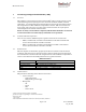
The side that has the three Ethernet connectors and two LEDs is referred to as the “bottom”.
Even though the connectors are weatherproof, IBR should be mounted with the connectors
facing downward for maximum environmental protection.
2.4 Power Requirements
IBR must be powered via PoE
+
through the RJ-45 connector labeled Port 0. Applying PoE
+
through any of the other Ethernet connectors will cause no harm, but will not power IBR.
Operating at full RF power, IBR requires less than 25.5 watts, thereby conforming to the IEEE
802.3at Type 2 standard for PoE
+
.
IBR does not have a capability to provide PoE to other devices on the network.
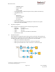
IBR may be powered by a FastBack power injector or by the PowerDsine 9001GO Power over
Ethernet (PoE) single-port Midspan injector.
2.5 Technical Assistance
In the event there is a problem with IBR or other equipment provided by Fastback Networks
( e.g., it arrives damaged or incomplete, or appears to not work properly), the operator
should contact Fastback Networks’ service center via telephone or email and be prepared to
provide:
o Product type and serial number
o Product service history (e.g., when was it received, how long has it been in service,
other relevant information)
o Description of the problem
o Customer contact information
Fastback Networks’ Customer Service can be reached by email at
customer.service@fastbacknetworks.com, or by telephone at (408) 430-5440 & select the
Service option.
3. Communicating with IBR
IBR has no external or internal keypads, switches, dials, knobs, or other physical controls.
Therefore, an operator will require a smart terminal, computer, workstation, or other such
device to communicate with IBR using command line interface and accessing IBR via any of
the Ethernet ports using Telnet or SSh or via the serial console port.
3.1 Access Control
IBR can be configured to require a valid user ID and password for access. Two levels of
access can be established: minimum functionality and full functionality. Detailed instructions
for controlling access to IBR are contained in the CLI Guide.
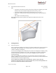
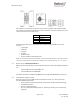
3.2 Serial Console
IBR has a four-pin connector that provides a serial interface for connection to a local
operator terminal. This interface typically will be used by an operator to communicate with
and control the IBR during preconfiguration and troubleshooting or at other times when a
local operator needs to communicate with IBR other than over an Ethernet link.
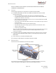
The mating cable that is provided with IBR has a DB9 connector on the other end. The
illustrations below show the pinouts of the two connectors and the cable wiring scheme.