
Installation Guide

IBR Installation Guide
Page 8 of 32 Doc # 770-00001-3
Aug. 30, 2013
DO NOT ATTEMPT TO APPLY POWER TO AN IBR THAT SHOWS SIGNS OF DAMAGE,
TAMPERING, OR MISHANDLING.
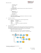
2.2 Inventory
The following components are required for successful installation of IBR:
(a) One IBR53, Model IBR-1000-38N and one IBR58, model IBR-1000-83N. Each IBR
includes the following:
o Three weatherproof RJ-45 cable-end connectors for CAT5E & CAT6 cables
*
;
o A weatherproof cap for the four-pin serial connector that is attached to IBR when
the IBR serial connector is not in use
*
.
o Two weatherproof caps for RJ-45 connectors that are attached to IBR when the IBR
RJ-45 connectors are not in use
*
.
o A two-meter serial cable with a DB-9 connector on one end and a four-pin connector
on the other end;
o Six crimp-on ends for RJ-45 connectors & instructions
o An information sheet for accessing regulatory documents and manuals on line;
o A quick reference guide;
o A warranty registration card;
*
Note: For proper operation of IBR, the weatherproof integrity of all cables and connectors
should be maintained and weatherproof caps should be firmly installed on unused
connectors at all times.
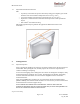
(b) A mounting bracket for each IBR. Fastback Networks can supply two types: (a) a fixed
wall/pole mount, model IBR-AC-BRP, and (b) an articulating wall/pole mount, model
IBR-AC-BRA.
(c) A PoE+ injector for each IBR; model IBR-AC-PON.
(d) A PoE Injector Mounting Kit, model IBR-AC-POM for each IBR.
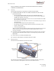
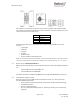
2.3 External Features
The illustration below identifies external features of IBR.
The side where the mounting lugs and serial port are located is referred to as the “back”,
since it is the side that will be against a wall or mast when IBR is mounted.