
Installation Guide

IBR Installation Guide
Page 24 of 32 Doc # 770-00001-3
Aug. 30, 2013
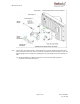
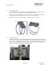
6.4 Connecting Power & Ethernet
When IBR has been securely mounted, connect a PoE
+
source to Port 0. The power indicator
LED will turn green when power is applied. If the PoE
+
source is also connected to an
Ethernet source, data will flow through IBR’s Ethernet Port 0.
If the power indicator LED does not illuminate when the power connection is made, consider
the following:
o Is the PoE connection secure?
o Is the power source receptacle hot?
o Are the cables of the proper type (CAT5E or CAT6)?
o Are the cables in good working order? (Cables should be certified.)
o Is the power brick good?
o Is the IBR working properly?
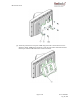
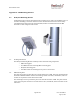
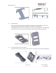
The RJ-45 Ethernet connectors on IBR will mate with the GT225360-00 connector from GT
Contact Co. LTD. An exploded view of the connector is shown below.
The connector will work with CAT5E and CAT6 cables and other cables having an
outer diameter between 5.0 and 6.0 mm. NOTE: Use only weatherproof, shielded
cable.
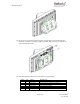
To assemble the connector:
o Strip the cable jacket 12.0 mm.
o Thread the cable through the connector components in the order shown.
o Insert the cable strands into the RJ-45 plug until tight.
o Assemble the connector, tightening the gland nut to within 9.0 – 10.0 kgf-cm
2
.
Three (3) Ethernet connectors ship with each IBR. Additional connectors may be obtained
from Fastback or directly from the manufacturer:
Model: GT225360-00
Supplier: GT Contact Co. LTD.
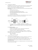
6.5 Connecting The Serial Port (Optional)
A local operator can communicate with IBR by connecting a suitable device to the four-pin
serial console connector on back of IBR. (See the section titled “Serial Console”.)
A local operator can configure IBR by connecting the Fastback-supplied serial cable to a PC
with a DB-9 RS-232 connection. If such a connection is not available, a USB-to-serial
converter may be used.
NOTE: When the serial port is not in use, a weatherproof protective cover should be installed
over the serial connector on IBR.