Intelligent Backhaul Radio Installation & Operation Manual Fastback Networks, Inc. 2460 N First St. #200 San Jose, CA 95131 U.S.A. (408) 430-5440 www.fastbacknetworks.com Doc # 770-00001-3 Aug.
IBR Installation Guide PURPOSE This Installation Guide provides detailed information related to initial configuration and installation of Fastback Network’s Intelligent Backhaul Radio (“IBR”). Supporting information is contained in the IBR Administration & Command Line Interface Guide (“CLI Guide”). Table of Contents Federal Communications Commission (FCC) Compliance Statement 1. Introducing Intelligent Backhaul Radio (“IBR”) 1.1 1.2 1.3 1.4 1.5 1.6 1.7 2. Overview......................................
IBR Installation Guide 4.18 Establishing A Radio Link ............................................................................................................................... 18 5. MAC Address Table & Counters 5.1 5.2 6. Installing IBR 6.1 6.2 6.3 6.4 6.5 6.6 6.7 7. 18 MAC Address Table........................................................................................................................................ 18 Counters .............................................................
IBR Installation Guide Federal Communications Commission (FCC) Compliance Statement This equipment has been tested and found to comply with the limits for a Class B digital device pursuant to Part 15 of the FCC Rules. These limits are designed to provide reasonable protection against harmful interference when the equipment is properly installed and operated in accordance with instructions contained in this manual. The equipment should not be operated if it becomes out of compliance with FCC Rules.
IBR Installation Guide 1. Introducing Intelligent Backhaul Radio (“IBR”) 1.1 Overview IBR combines a Carrier Ethernet switch and an SC-FDE1 radio in a small, passively-cooled, environmentally protected package for use in 4G cellular backhaul and fiber extension applications. It is designed for small cell deployment in dense urban environments where line of sight between radios is difficult or impossible to achieve.
IBR Installation Guide o o o o o o 1.5 - SNMP MIB support - Interface-MIB - MIB II - Enterprise MIB Packet-based timing – 1588v2 transparent clock w/submicrosecond latency QinQ (IEEE 802.1ad) QoS - Eight queues - 802.1p classification - Strict scheduling - PIR shaping 256 bit AES encryption Physical link and network layer redundancy for maximum service uptime Service protection and reliability Regulatory Compliance IBR is compliant to the applicable portions of the following standards.
IBR Installation Guide 1.7 Physical & Environmental Features IBR: o o o o Is passively cooled and can operate continuously at full power and duty cycle under maximum solar load at ambient temperatures from -40o C to +60o C. Can be stored safely at temperatures in the range from -55o C to +85o C. Experiences a wind load of less than 300N when exposed to a wind speed of 265 km/hr. Has an IP668 environmental rating. IBR weighs approximately 4 kg and has the approximate dimensions shown in the illustration.
IBR Installation Guide DO NOT ATTEMPT TO APPLY POWER TO AN IBR THAT SHOWS SIGNS OF DAMAGE, TAMPERING, OR MISHANDLING. 2.2 Inventory The following components are required for successful installation of IBR: (a) One IBR53, Model IBR-1000-38N and one IBR58, model IBR-1000-83N. Each IBR includes the following: o Three weatherproof RJ-45 cable-end connectors for CAT5E & CAT6 cables*; o A weatherproof cap for the four-pin serial connector that is attached to IBR when the IBR serial connector is not in use*.
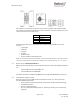
IBR Installation Guide The side that has the three Ethernet connectors and two LEDs is referred to as the “bottom”. Even though the connectors are weatherproof, IBR should be mounted with the connectors facing downward for maximum environmental protection. 2.4 Power Requirements IBR must be powered via PoE+ through the RJ-45 connector labeled Port 0. Applying PoE+ through any of the other Ethernet connectors will cause no harm, but will not power IBR. Operating at full RF power, IBR requires less than 25.
IBR Installation Guide This interface can be used by an operator only to control, configure, and troubleshoot IBC, but not for general network connectivity or data transmission. Pin-outs of the four-pin serial connector are shown in the table below.
IBR Installation Guide Detailed information can be found in the CLI Guide. 3.5 Antennas The radome on top of IBR houses transmit and receive antennas that face outward through the flat sides of the radome. The direction in which the antennas are pointed can be changed only by changing the orientation of the IBR itself. The CLI-based pointing tool can be used as an aide to orient IBR for best link performance. IBR is not designed to be used with external antennas. 3.
IBR Installation Guide To avoid the possibility of damaging an IBR by overdriving the front end of the receiver, prior to connecting a power source, position the radios so that they are tilted away from each other, facing downward, and separated by at least one meter. Check the RSSI using the following CLI command in the Global Config mode: IBR58 (config) # interface radio 0 status RSSI should be -20dB or less. If RSSI is greater than -20 dB (e.g., -17dB, -15dB, etc.
IBR Installation Guide 4.6 Confirming VLAN Settings By default, VLAN functionality is enabled on IBR and all interfaces are assigned to VLAN1. During initial configuration, the operator should assign VLANs to interfaces as desired. IBR can be managed using any VLAN to which an IP address is assigned. See the section titled Separating Management Traffic From Data Traffic for details on assigning an IP address to a VLAN and using VLANs to segment management traffic from data traffic.
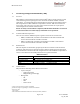
IBR Installation Guide Prompt IBR58 (config)# IBR58 (config-vlan-1)# IBR58 (config-vlan-1)# IBR58 (config)# IBR58 (config-vlan-2)# IBR58 (config-vlan-2)# IBR58 (config-vlan-2)# IBR58 (config) # IBR58 (config-vlan-823) # IBR58 (config-vlan-823) # IBR58 (config) # Command interface vlan 1 ip address 192.168.128.158 255.255.255.0 exit interface vlan 2 no shutdown ip address 10.22.12.201 255.255.0.0 exit interface vlan 823 ip address 10.1.1.158 255.255.0.
IBR Installation Guide Prompt Command IBR58 # show vlan brief VLAN Name Status Native Allowed ---- ---------------- --------- ---------------- --------------------------------------------1 VLAN1 active ge0 ge0 2 VLAN2 active ge1 ge2 ge3 ge1 ge2 ge3 823 VLAN823 active ge3 ge3 IBR58 # 4.8.6 Remarks Confirm that the interfaces were correctly configured.
IBR Installation Guide One use of this interface is to allow a user to send ping packets to the opposite IBR to verify link integrity. This VLAN has no exposure to a physical network interface so traffic on this VLAN is isolated from the network. 4.9 Saving New Configuration Use the following commands to save the new settings to the startup configuration file. IBR58 (config)# copy running-config start-up config 4.
IBR Installation Guide 4.14 Configuring IBR Name Server The following command can be used to configure the Name server. IBR58 (config)# ip name-server [ip-address} 4.15 Configuring IBR NTP Server The following command can be used to configure the NTP server. IBR58 (config)# ntp server [ip-address} 4.16 Configuring IBR SNMP Server The following sequence of commands can be used to configure the SNMP server.
IBR Installation Guide IBR58 (config) # 4.18 Establishing A Radio Link IBRs will automatically establish a link using the best frequencies to optimize data throughput. IBR has a software feature called “Pointing Tool” that will aid in quickly and properly aligning IBRs for best link performance. It will not be necessary to use this feature in a laboratory setting where the two ends of a link are within sight of one another.
IBR Installation Guide (p) Jabbers ------------------ Frames longer than 1518 octets (q) Single-Col # of times only one collision occurred before successful xmsn (r) Multi-Col --------------- # of times multiple collisions occurred before successful xmsn (s) Late-Col Collisions detected after > 512 bits sent (t) Excess-Col -------------- Frames not sent due to excess # of retries (u) Drops TX queue drops (v) Octets ------------------ TX queue octets (w) Packets TX queue packets 6. Installing IBR 6.
IBR Installation Guide 6.2 Safety Considerations o Ensure that grounding is in accordance with local codes. o Use lifting methods and/or equipment that are appropriate for the location; e.g., pole climbing equipment, ladder, power lift. o Note the locations of other equipment, power lines, vehicle traffic, and other potential safety hazards at the installation site. 6.3 Mounting IBR IBR must be mounted on a suitable bracket that will hold IBR securely under all environmental conditions.
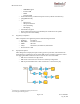
IBR Installation Guide 6.3.3 Fixed or Non-articulating Bracket – The fixed bracket can be rotated in the horizontal plane when mounted to a pole, but cannot be rotated in any direction when mounted on a wall. The following diagrams are a guide for assembling the non-articulating mount and attaching it to IBR. (1) Attach the IBR plate to IBR as shown below. Screws # 3 should be torqued to a maximum of 10 ft-lbs (138 kgf-cm). Page 21 of 32 Doc # 770-00001-3 Aug.
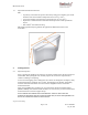
IBR Installation Guide (2) Attach the pole bracket to the plate on IBR using the hooks as shown in the next two diagrams. NOTE: If IBR will be attached to a wall, the pole bracket should be turned so that the pole side faces IBR and the flat side faces outward. Page 22 of 32 Doc # 770-00001-3 Aug.
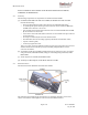
IBR Installation Guide (3) Use screws to secure the two plates together as shown below. Screws #4 should be torqued to a maximum of 5 ft-lbs (69 kgf-cm). (NOTE: IBR is shown inverted from the way it should be mounted.) (4) Materials provided with this mount are shown in the table below. ITEM # 1 2 3 4 5 6 QTY 1 1 4 2 4 2 PART # 430-00014 430-00016 470-00007 470-00008 495-00001 495-00002 DESCRIPTION Bracket, IBR Pole/Wall Mount, Wall Plate Bracket, IBR Pole/Wall Mount, IBR Plate Screw, M8x1.
IBR Installation Guide 6.4 Connecting Power & Ethernet When IBR has been securely mounted, connect a PoE+ source to Port 0. The power indicator LED will turn green when power is applied. If the PoE+ source is also connected to an Ethernet source, data will flow through IBR’s Ethernet Port 0.
IBR Installation Guide 6.6 Establishing A Link Except in the most severe cases of in-band interference, a pair of IBR’s will automatically select the best combination of channel frequencies and bandwidth for a link. (a) Wait for radios to finish booting and establishing a link. (b) Use the CLI command shown below to verify that a link has been established.
IBR Installation Guide The SNMP agent will support MIB-II (RFC 1213), IF-MIB11(RFC 2863), and a Fastback enterprise MIB. Detailed information for configuring SNMP is contained in the CLI Guide. IBR sends traps supported by Fastback MIB, DISMAN-EVENT-MIB, and NET-SNMP-MIB. SNMP polling for traps takes up to sixty (60) seconds. 7.4 Switching & Transport IBR supports 802.1Q (VLAN). 7.5 Data Handling IBC supports the following OSI12 Layer 2 standards: o IEEE 802.3ab (Gigabit Ethernet); o IEEE 802.
IBR Installation Guide IBR will avoid synchronizing to a server whose time might not have been synchronized or to one whose time is significantly different than the time from other associated servers, even if its stratum is lower. When NTP is enabled on IBR, NTP time will take precedence over time provided by any other source or method. 7.
IBR Installation Guide Appendix A – IBR Mounting Brackets A 1. Wall/Pole Mounting Bracket Fastback Networks’ wall/pole mounting bracket assembly can be used to mount IBR on poles, on the sides of buildings, or in other outdoor locations. The first illustration below shows a fully assembled bracket with pole straps attached to IBR, and the second illustration shows IBR mounted on a mast using the same bracket. 1.1.
IBR Installation Guide 1.3. Wall/Pole Plate The plate shown below attaches to the IBR mounting plate for mounting IBR on a pole or mast that is between one and six inches in diameter, or on a wall or other structure. When IBR will be mounted on a wall, the flat side of this plate will be against the wall. When IBR will be mounted on a mast, the flat side of this plate will be against the IBR mounting plate. 1.4.
IBR Installation Guide 1.5. Pole mounting straps Mounting IBR on a pole or mast simply requires attaching pole bands to the bracket as shown below. Be careful to not damage the bracket when tightening the bands. Pole straps can be attached either to the ends of the plate or to the flanges in the center of the plate as appropriate for the diameter of the mast to which it is being attached. Pole bands are not included. The bracket will accept steel bands up to ¾” wide. 1.6.
IBR Installation Guide The installer can attach a rope or hook to one of the holes on the side of the mounting bracket in order to hang IBR on a utility belt until it is time to attach it to the bracket. To aid in hanging IBR, the plate on IBR can be hooked onto the mating wall/pole plate while the two M6x10 mounting bolts are being tightened. An Allen wrench is needed to tighten the bolts. A 2.
IBR Installation Guide Page 32 of 32 Doc # 770-00001-3 Aug.