
Installation Manual

IBRInstallationGuide
Page20of40 Doc#770‐00001‐13
Sept.21,2014
Packets TXqueuepackets
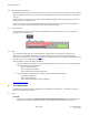
MCScounterscanbedisplayedusingthefollowingcommand:
IBR102#showinterfacesradio0status
Counterscanbeclearedusingthefollowingcommands:
IBR102#clearcountersmcs clearsmcscounters
IBR102#clearcountersradio clearsradiocounters
IBR102#clearcountersswitch clearscountersonallswitchinterfaces
IBR102#clearcountersgigabitEthernet[arg] argcanbe0,1,2,or3
ReturntoTableofContents
6. InstallingIBR
6.1 SafetyConsiderations
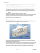
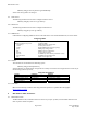
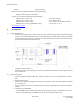
Ensurethatgroundingisinaccordancewithlocalcodes.IBRshouldbegroundedusingthegroundlug
connectoronthebackofIBRwithalugsuchasPanduitTwo‐HoleStandardBarrelCopperLug,Panduit
part#LCD6‐14A‐L(shownbelow).Notethatsincethegroundinglugmountsbetweenthefins,anylug
greaterthan0.48inchesinwidthwillnotfit.
Useoverheadworkmethodsand/orequipmentthatareappropriateforthelocation;e.g.,climbing
equipment,ladder,manlift,etc.
Notethelocationsofotherequipment,powerlines,vehicletraffic,andotherpotentialsafetyhazardsat
theinstallationsite.
6.2 InstallationChecklist
ApretestedandpreconfiguredIBR.Note:Alinkwillrequireoneeachofa5.5GHzIBRanda5.7GHz
IBR.
IBRmountingbrackets.
APoE
+
sourcecapableofsupplyingatleastthirty‐five(35)wattstotalontwopairs(pins4&5and7&8)
oronallfourpairs.
AsurgesuppressorthathasbeenvalidatedtofunctionproperlywithIBR,suchasTransectorModelT‐
419899.
MaterialsforgroundingIBR:
‐ GroundingIBRrequiresterminatingthetwo‐holegroundlug,whichwillaccommodatetwoeach12‐
24x1/2”orM6groundtaps.TheIBRchassishastwopre‐tappedholesforthislug.