
Installation Manual

IBRInstallationGuide
Page12of40 Doc#770‐00001‐13
Sept.21,2014
3.6 ExternalEthernetConnectors
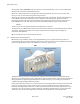
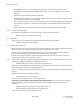
IBRhasthreeRJ‐45connectorslocatedonthebottomoftheunit,asshownintheillustrationinthepreceding
section.BeginningwiththeportnearesttheLEDs,theGigabitEthernetportsarenumbered0,1,and2(ge0,
ge1,ge2).
AllthreeEthernetconnectorscanbeusedfortrafficandIBRmanagementdata,butonlytheonenearestthe
LEDs(ge0)canpowerIBRviaPoE+.
TheRJ‐45connectorswillacceptshieldedandbondedRJ‐45typematingconnectorswithaweatherproof
seal.ItisessentialthatonlyweatherproofconnectorsbeconnectedtoIBR.
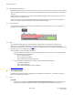
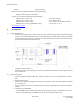
3.7 PowerConnector
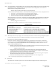
Powermustbeconnectedtoge0asshowninthegraphicbelow.Connectingpowertoge1orge2willnot
harmIBR,butwillnotpowerit.
3.8 LEDs
TwoweatherproofLEDsthataremountedadjacenttoge0provideavisualmeansforanoperatorto
determinethestatusofIBR.BothLEDscanbedeactivatedviatheCLI.SeetheCLIGuidefordetailed
information.TheLEDscanbeseenintheIBRimage.TheLEDnearesttothecoolingfinsistheradioLEDand
theLEDnearesttotheradomeisthesystemLED.
WhentheLEDsareactive(thedefaultcondition):
TheupperLED(whentheLEDsareontheleftfromtheviewer’sperspective)isasystemindicatorand
willprovidethefollowinginformation:
‐ Off:Systemhasnopower.
‐ Amber:Bootloaderactivated.
‐ Green:FastbackOperatingSystemloaded.
ThelowerLEDistheradioindicatorandwillprovidethefollowinginformation:
‐ Off:Radionotinitialized.
‐ Amber:Radioinitialized.
‐ Green:Radioinitializedandalinkestablished.
ReturntoTableofContents
4. PreconfiguringIBRs
ThefollowingprocedureisforpreconfiguringapairofIBRspriortoinstallation.ConsulttheCLIGuideas
necessaryfordetailedinformation.
4.1 Power
CAUTION:
Whenpowerisapplied,theradiosautomaticallywillbegintransmittingwithinsixty(60)seconds.
ToavoidthepossibilityofdamaginganIBRbyoverdrivingthefrontendofthereceiver,priorto