
Install Instructions


Page 4 of 4 www.fast-stat.com
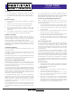
R C W
G
Thermostat
Y2Y1
Y2
O/B
Thermostat
Cable
Red
Black
Orange
Blue
Black
White
Yellow
Brown
Brown
Yellow
White
Orange
Gray (x2)
Blue
Black
Black
Red
Green Loop
Purple Loop
Indoor Unit
Heat
24V Transformer
R C
Fan Control
GW
R C W
Y1
Heat Pump
Defrost
Rev.
Valve
Stage 1
Y1
Stage 2
Y2
Control Board
O/B
Condenser
Cable
External Transformer
24V Transformer
40
50
60
70
80
90
100
Thermostat
(Optional)
Heat Pump
Module
Model 9000
Heat Pump
Indoor Unit
Module
Model 9000
Indoor Unit
Two Transformer Wiring
B
Note: After installing the external transformer, follow the
‘Transformer Test’ section to ensure it is in parallel with
the indoor unit’s transformer.
Note: See the ‘Fossil Fuel or Supplemental Heat’ section
for details on the green and purple wire loops and
optional thermostat.