
Install Instructions

Page 4 of 4 www.fast-stat.com
Brown
Yellow
White
Orange
Gray (x2)
Blue
Black
Black
Red
40
50
60
70
80
90
100
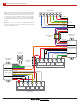
Thermostat
(Optional)
Green Loop
Purple Loop
R C W
Heat Pump
Defrost
Rev.
Valve
Stage 1
Y1
Stage 2
Y2
Control Board
O/B
Condenser
Cable
External Transformer
24V Transformer
Sender
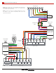
Yellow
Green
White
Brown
Red
Black
Blue
Gray
Red
Black
Purple
R
C
W
G
Thermostat
Y2 Y1
Y2
O/B
Thermostat
Cable
Black
Red
Orange
Purple
Gray
Red
Black
Black
Blue
White
Green
Brown
Indoor Unit
Heat
24V Transformer
R C
Fan Control
GW
Indoor Unit
Module
Model 7000
Indoor Unit
Rev.
Valve
O/B
Heat Pump
Module
Model 7000
Heat Pump
Two Transformer Wiring
B
Note: After installing the external transformer, follow the
‘Transformer Test’ section to ensure it is in parallel with
the indoor unit’s transformer.
Note: See the ‘Fossil Fuel or Supplemental Heat’ section
for details on the green and purple wire loops and
optional thermostat.