
Install Instructions

Page 3 of 4 www.fast-stat.com
Sender
Yellow
Green
White
Brown
Red
Black
Blue
Gray
Red
Black
Purple
R
C
W
G
Thermostat
Y2 Y1
Y2
O/B
Thermostat
Cable
Red
Black
Orange
Purple
Gray
Red
Black
Black
Blue
White
Green
Brown
Brown
Yellow
White
Orange
Gray (x2)
Blue
Black
Black
Red
Green Loop
Purple Loop
Indoor Unit
Heat
24V Transformer
R C
Fan Control
GW
R C W
Heat Pump
Defrost
Rev.
Valve
Stage 1
Y1
Stage 2
Y2
Control Board
O/B
Condenser
Cable
Indoor Unit
Module
Model 7000
Indoor Unit
Heat Pump
Module
Model 7000
Heat Pump
Rev.
Valve
O/B
40
50
60
70
80
90
100
Thermostat
(Optional)
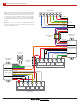
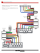
Grounded Commons Wiring
A
Note: The Indoor Unit Module and Heat Pump Module
must both have a black wire grounded, otherwise the
Heat Pump Module will not receive power. If there is
a extra wire in the condenser cable, it can be used
to connect the black wire on the Indoor Unit Module
and Heat Pump Module together instead of grounding
them.
Note: See the ‘Fossil Fuel or Supplemental Heat’
section for details on the green and purple wire loops
and optional thermostat.