
Install Instructions

Page 4 of 4 www.fast-stat.com
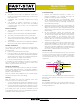
Before After
Thermostat
R
G
G
Fan
YR C
Indoor Unit
Sender
Purple
Red
Black
Yellow
Green
Purple
Green
Yellow
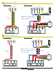
Thermostat
Cable
Broken
Wire
Thermostat
Cable
Y
Thermostat
G
Y
RH
24V Transformer
G
Fan
H
Humid.
YR C
Indoor Unit
24V Transformer
To Air
Conditioner
To Air
Conditioner
Receiver
Model
1000
Note: If the installation has additional
wires (W2, Y2, O/B, H, etc), they can
remain connected directly to the
equipment terminals.
Repairing a Broken Wire
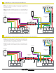
F
Upgrading from a Single-Stage Air Conditioner to a Single-Stage Heat Pump
E
C R
W
Heat Pump
Y
Comp.
Control
Board
Rev.
Valve
O/B
Indoor Unit
W
Heat
G
Fan
Y
Red
Black
Purple
Yellow
Green
Condenser
Cable
24VAC
Relay
C
R
24V Transformer
Green
Yellow
Purple
Sender
Note: A 24V relay is required to electrically isolate the heat
pump from the indoor unit.
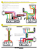
Note: If the heat pump does not need a ‘W’ connection, the
wiring from diagram C or D can be used with the green wire
connected to ‘O/B’.
Note: An external 24VAC transformer and 24VAC relay will have
to be installed.
Receiver
Model
1000
W
R
Thermostat
GY
Thermostat
Cable
O/B
External Transformer
24V Transformer