Manual GA450 V. 2.2 Fast & Fluid Management B. V. PO Box 220 2170 AE Sassenheim The Netherlands www.fast-fluid.
© Fast & Fluid Management B.V. This manual or parts thereof may not be reproduced, stored in a retrieval system, or transmitted, in any form or by any means, electronic, mechanical, photocopying, recording, nor otherwise, without the prior written permission of Fast & Fluid Management B.V. This manual could contain technical inaccuracies or typographical errors. Fast & Fluid Management B.V.
Table of Contents Table of Contents 1 2 3 About this manual......................................................................................................... 5 1.1 How to work with the manual .......................................................................................... 5 1.2 Record of changes ......................................................................................................... 5 Safety ...........................................................................
Table of Contents 4 5 6 Installation ................................................................................................................... 21 4.1 Unpack the machine ..................................................................................................... 21 4.1.1 Remove the cardboard....................................................................................... 21 4.1.2 Remove the plastic protection and foil .............................................................
About this manual 1 GA450 V. 2.2 About this manual The manual shows the information necessary to: - install - operate - perform basic maintenance - correct small problems The GA450 and all its versions are referred to in the manual as the ’machine’. This manual contains the original instructions. The original language of the manual is English. 1.1 How to work with the manual 1. Familiarize yourself with the structure and content. 2.
About this manual GA450 6 V. 2.
Safety 2 GA450 V. 2.2 Safety WARNING Read the manual before you install or use the machine. Failure to do so can result in personal injury, death or property damage. 2.1 Intended use The machine is designed to mix paint in a can. Any other use of the machine is strictly forbidden. 2.2 Liability Our machines and accessories are fully compliant with the CE regulations. Any modification can result in not fulfilling the CE safety requirements and is therefore not allowed. Fast & Fluid Management B.V.
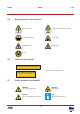
Safety 2.5 GA450 V. 2.2 Safety symbols on the machine /i Read the manual. Electrical hazard. Read the manual. Central earthing point. Pinch hazard. Electrical hazard. Rotating parts. On-Off 2.6 Labels on the machine /i When can diameter > Ø39 cm : remove shield Upper and lower shield instruction. When can diameter > Ø40,2 cm and height <28 cm : use adapters 2.7 Safety symbols in the manual /i WARNING Can cause personal injury. WARNING Pinch hazard.
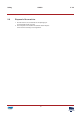
Safety 2.8 GA450 Disposal of the machine 1. Sort the machine, the accessories and the packaging for environmentally friendly recycling. 2. Do not dispose of the machine into domestic waste. Dispose of the machine according to local regulations. 9 V. 2.
Safety GA450 10 V. 2.
Operator manual GA450 3 Operator manual 3.1 Description 3.1.1 Overview of the machine L V. 2.2 M K C D B A J I E H G A: B: C: D: E: F: G: H: I: J: K: L: M: Door Casing Control panel. See also § 3.1.2. Emergency stop Wheel Adjustable foot Can plate (bottom) 11 Can table Drain orifice Can plate (top) Type plate. See also § 3.1.4.
Operator manual 3.1.2 GA450 Overview of the control panel A: B: C: D: E: F: G: Stop/Up key Program key T1 key (Time 1) T2 key (Time 2) T3 key (Time 3) S-key (mix speed) Display B Type plate: serial number Fast & Fluid Management B.V. IDEX Dispensing FAST& FLUID P.O. Box 220 2170 AE Sassenheim THE TINTING COMPANY The Netherlands Model XXXXX-XXX Prod. Week XX-XXXX Serial No. XXXXX-XX-XXXXXX 3.1.4 Type plate: details Fast & Fluid Management B.V. IDEX Dispensing FAST& FLUID P.O.
Operator manual 3.2 GA450 V. 2.2 Operation WARNING Only push the emergency stop in the case of a safety emergency. 3.2.1 Turning on the machine 1. Connect the power cable to the grouned wall socket. 2. Make sure that the emergency stop is released. 3. Set the Main switch to ‘ON’. When the machine is on, you hear two ‘beeps’ and the display shows ‘...’. 4. Press the Stop/Up key. When the machine is operational, the display shows ‘rdY’. 3.2.
Operator manual GA450 V. 2.2 Place the can 1. Put one or more cans (A) in the centre of the can table, or in a pattern that has its gravitational centre in the middle of the can table. WARNING It is possible that the can is heavy. Use the correct lifting tool when appropriate. Obey the local regulations. A 1 A 3 CAUTION Make sure that all cans have the same height. Do not stack cans upon each other. A Note When the diameter of the can is > Ø39 cm, remove the upper shield.
Operator manual GA450 V. 2.2 Close the door 1. Pull up the handle (A) to unlock the can table. 2. Push the can table (B) inwards until you hear a ‘click’. The can table is locked. 3. Close the door. B 2 3.2.5 1 A 1 A Start the machine 1. Push the T1, T2 or T3 key and select the mix time. See the table below. The machine automatically clamps the can and operates for the chosen time. See § 3.2.8. Note The display shows the time in seconds that remain before you can open the door.
Operator manual 3.2.7 GA450 Stop the operation manually 1. Push the Stop/Up key. 2. Wait until the can plates are open. 3. If necessary, remove the can. See § 3.2.6. 3.2.8 Adjust the mix speed Note The machine controls the mix speed based on the size of the can. For some cans it might be necessary to adjust the mix speed. Contact you paint supplier. Note You can adjust the mix speed when the display shows ‘rdY’. 1. Push the S-key. The display shows the last-chosen speed. This is the default mix speed.
Operator manual GA450 V. 2.2 250 SP4 200 SP3 150 SP2 SP1 100 A (rpm) 50 0 10 20 30 40 B (cm) Switch point 3 Switch point 2 Switch point 1 A: Speed (rpm) B: Can height (cm) Note The mix speed depends on the can height. 3.2.
Operator manual GA450 Note The table shows the default values. Note You can adjust the default mix time when the display shows ‘rdY’. 1. At the same time, push the Program key and the T1, 2 or 3 key. 2. Push the + or - key to adjust the mix time for T1, 2 or 3. 3. To save the new mix time, push the S-key. 4. If you do not want to save the new mix time, push the Stop/Up key. 3.3 General cleaning: after every operation 1. Clean the machine with a cloth and remove all spilled paint or other liquid.
Operator manual 3.6 GA450 V. 2.2 Remove spilled paint Do this procedure when paint is spilled inside the machine. 1. Make sure that the machine is stopped. See § 3.2.5 or § 3.2.7. 2. Put a reservoir (A) below the drain orifice (B). CAUTION Make sure that the reservoir is big enough to hold all the spilled paint. 3. Remove the cap (C) from the drain orifice. The spilled paint comes out of the machine. 4. Dispose of the spilled paint according to local regulations. 5. Install the cap to the drain orifice.
Operator manual GA450 20 V. 2.
Installation 4 Installation 4.1 Unpack the machine 4.1.1 Remove the cardboard GA450 1. Remove the tensioning straps (A). 2. Remove the cardboard (B). V. 2.2 A B 4.1.2 Remove the plastic protection and foil 1. Remove the plastic protection (A). 2. Remove the plastic foil (B).
Installation 4.1.3 GA450 V. 2.2 Remove the transport brackets 1. Remove the screws (A). 2. Remove the transport brackets (B). 12mm B A 4x 4.1.4 Dispose of the packaging material 1. Dispose of the packaging material in an environmentally friendly way, according to local regulations. 4.2 Put the machine in position 4.2.1 Move the machine from the pallet 1. Place the optional ramp (A). 2. Push the machine from the pallet on to the ground. CAUTION Do not use a fork-lift truck.
Installation 4.2.2 GA450 V. 2.2 Move the machine to the final location 1. Push the machine to the final location. CAUTION Do not use a fork-lift truck. Note Make sure the final location is sufficiently illuminated. 2. Connect the power cable to the net entry. 3. Connect the power cable to the wall socket. 4.2.3 Level the machine 1. Move down the adjustable feet (B) until the wheels (A) are off the ground. 2. Adjust the height of the feet and make sure that the machine is leveled. 3.
Installation GA450 24 V. 2.
Troubleshooting GA450 5 Troubleshooting 5.1 General troubleshooting procedure 1. Try to solve the problem with the information in this manual. See § 5.3.1. 2. If it is not possible to solve the problem with the information in this manual, contact service. See § 5.2. 5.2 Contact service 1. Find the type plate on the rear of the machine. See § 3.1.4. 2. Take a note of the model number and the serial number of the machine. 3. Contact your supplier or manufacturer. See www.fast-fluid.com. 25 V. 2.
Troubleshooting GA450 5.3 Troubleshooting guide 5.3.1 Easy-to-solve errors 5.3.2 5.3.3 V. 2.2 Problem Possible cause Possible solution The display shows ‘E00’ Emergency stop is pressed during idle state. Release the emergency stop. See § 5.4. The display shows ‘E01’ The door is open. Close the door. The display shows ‘E05’ The cradle lock failed to release the cradle. Reset the machine. See § 5.4. When the problem persists, contact service. See § 5.2.
Troubleshooting 5.3.4 5.4 GA450 Problem Possible cause Possible solution The display shows ‘E55’ Failed to run the mixer motor backward. Reset the machine. See § 5.4. When the problem persists, contact service. See § 5.2. The display shows ‘E56’ Failed to stop the mixer motor. Reset the machine. See § 5.4. When the problem persists, contact service. See § 5.2. The display shows ‘E57’ Failed to brake the mixer motor. Reset the machine. See § 5.4. When the problem persists, contact service.
Troubleshooting GA450 28 V. 2.
Technical data 6 Technical data 6.1 General specifications GA450 V. 2.2 /i 6.2 Parameter Specification Materials used are suitable for Water-, universal- and solvent colorants Maximum load weight [kg] 40 Can plate diameter [cm] 38 Can plate bottom seating diameter [cm] 36 Maximum can height [cm] 48 Minimum can height [cm] 7 Mix ratio [horzontal:vertical] 1:2 Dimensions and mass /i 6.
Technical data 6.5 GA450 V. 2.2 Safety classifications /i 6.
A B C D 1816799 CABLE 12 CABLE 12 1816797 CABLE 10 CABLE 10 BROWN BLUE BROWN BLUE 1816794 4 M CABLE 7 CABLE 7 4 1816800 CABLE 13 CABLE 13 CRADLELOCK DOORLOCK2 1816796 CABLE 9 CABLE 9 DOORLOCK1 321 2 3 3 OPTICAL SENSORS MIXERMOTOR 1 1816792 CABLE 5 CABLE 5 INVERTER DISPLAY/KEYBOARD 3 BROWN BLUE 1816791 CABLE 14 Tuesday, June 04, 2013 © Fast & FLuid Hub v. Doorneweg 31 PO Box 220 2170 AE Sassenheim The Netherlands 2 FAST & FLUID EARTH INVERTER HEATSINK Revnr.
Technical data GA450 32 V. 2.