Owner’s Manual NMEA2000 MG2000 Tachometer IS0189 rev.
Standard Operating Conditions Description Figure 1 Operation Normal Mode Display Contrast Displayed Functions Default screen 1 Default screen 2 Default screen 3 Default screen 4 Default screen 5 Figure 2 Default screens Figure 3 LCD Display Screens Index Edit Mode Functions that are adjusted in Edit Mode.
Calibrate Trim Sender Select Display Units Select “Pressure Units” Select “Volume Units” Select “Temperature Units” Select “Distance Units” Select “Depth Units” Fuel Tank Calibration Low Fuel Alarm Setting Adjust “Low Fuel Alarm” Setting Select “Self Test” Select “Software ID and Revision” Depth Sounder Warnings Set Depth Sounder Shallow Warning Set Depth Sounder Deep Warning Set Depth Sounder Keel Offset page 20 page 20 page 20 page 21 page 21 page 21 page 21 page 22 page 23 page 23 page 23 page 24 page 2
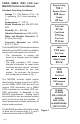
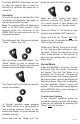
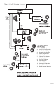
PGFXXX FARIA NMEA 2000 CAN bus MG2000 Tachometer Manual Oil Pressure On Off Standard Operating Conditions 20.1 PSI Voltage: 12 - 24V System, 19.3 PSI (10.5 – 32 V operating, 36 V max operating, 1 Hr.) 65˚ F Temperature: 0° - 158° F Shock Resistant per MIL-STD-202, 50G Oil Pressure On Off Humidity: 0% - 98% Rel 20.1 PSI Vibration Resistant per SAE J1455 19.
The Faria MG2000 Tachometer will turn on when the ignition key is turned on and will turn off when the ignition key is turned off. buttons to enter the “Edit” menus. Operation The unit will power up showing the “Self Test Mode Is In Operation” then switch to the last saved default screen. Note: The warning LEDs will flash when there is no ECU data present. If this happens check the connection to the NMEA 2000 bus and ensure the unit is connected properly.
data directly from Faria the ECU so no settings are required. KLine A microprocessormini controlled stepper motor moves Gateway the pointer to display engine revolutions per minute. With the display in “Positive” mode, black on white, pressing the “Down” button decreases the contrast. Pressing the Oil Pressure “Up” button increases contrast. Continuing to press the “Up” button causes the display to reverse to the “Negative” mode, white on black.
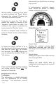
Default Screen “2” on the tachometer. Pressure gauge dial range can be selected in “Edit” mode. Fuel Left 47 Gal Default screen “4” Fuel Used 17.5 Gal On Off RPM 41˚21N 072˚06W 3400 Fuel Inst 11.6 GalPSI 19.3 Fuel Left F remaining Displays the quantity 65˚ of fuel in the fuel tank based on the original quantity of fuel in Faria the tank when full and KLine the amount of fuel used based on the GPH from the engine miniECU and the time spent at each GPH.
Engine !” or “Engine Emergency Stop !”. Accessing the “View“ mode when the Alarm screen appears will allow more information to be displayed about the alarm, if provided by the engine. Internal alarm values can be set for “Low Fuel” and other functions. Alarms for these settings will appear as required.
1. 2. 3. 4. 5. 6. 7. 8. 9. 10. 11. 12. 13. 14.
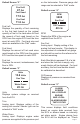
Edit Mode The “Edit” mode is used to adjust or set the values of numerous functions and options in the MG2000. The procedure below specifies the steps to be taken in the “Edit” mode to adjust / set each option. To enter “Edit” mode, press “Mode” and “Up” buttons while in “Normal” mode. To return to “Normal” mode, press “Mode” button once while in “Edit” mode. Functions that are set or adjusted in the “Edit” mode. 1. 2. 3. 4. 5. 6. 7. 8. 9. 10. 11. 12. 13. 14.
Instructions – Function Select Default Screen LINE 1 2 3 DISPLAY Select Default Screen 1 Default 2 Display 3 Screen: 4 1 1 Default 2 Display 3 Screen: 4 X 1 2 3 Local Fuel Config 1 2 3 Reset Fuel Used Press and hold “Up” and “Down” for 2 seconds to select “Default Screen.” Press “Up” or “Down” to select another function or “Mode” to return to “Normal” mode. (Display Screen 1 is the “Default” at first turn on.
Press and hold “Up” and “Down” for 2 seconds to reset “Fuel Used” to zero (0). Automatically resets fuel used to zero and returns to “Local Fuel Config” menu. Press “Up” or “Down” to select another function or “Mode” to return to “Edit” mode. Set “Fuel Tank Full” 1 2 3 Set Fuel Tank Full 1 2 3 Set Amount of Fuel 1 2 3 Fuel Amount XXX NOTE: In order to use the “Fuel Left” function, the owner must set this function when the fuel tank is filled or use the set current amount of fuel below.
When the volume is correctly set, Press and hold “Up” and “Down” for 2 seconds to save the value and return to the “Local Fuel Config” mode. Press “Up” or “Down” to select another function or “Mode” to return to “Edit” mode.
Press “Up” or “Down” to set the fuel tank size displayed on the Screen to match your fuel tank size. Line 4 value will adjust. When set, Press and hold “Up” and “Down” for 2 seconds to save the value. 1 Select 2 Other 3 Fuel Tank 4 XX 1 2 3 Fuel Totalizer Config 1 2 3 Reset TFuel Used 1 2 3 Set TFuel Tank Full Press “Up” or “Down” to select a different function or press “Mode” to return to “Local Fuel Config” menu.
Press and hold “Up” and “Down” for 2 seconds to set “TFuel Tank Full.” Automatically sets the total fuel available to the TFuel tank size selected by the user and returns to “Fuel Totalizer Config” menu. Press “Up” or “Down” to select another function or “Mode” to return to “Edit” mode. Total Amount of Fuel 1 2 3 Total Amount of Fuel 1 Fuel Amount XXX NOTE: If the known combined amount of fuel is in the fuel tanks but they are not full, this function can be used to indicate the amount of fuel available.
1 2 3 4 5 6 Select TFuel Tank Size 120 Gal > 25 Gal 36 Gal 40 Gal 50 Gal 55 Gal 80 Gal 1 2 3 4 Select Other TFuel Tank Size Press “Up” or “Down” until the combined size of all fuel tanks is displayed on the Screen. Line 4 value will adjust. 1 Select 2 Other When set, Press and hold “Up” and “Down” for 2 seconds to save the value. 3 Fuel Tank 4 XX 1 2 3 Set Totalizer Mode Press “Up” or “Down” to scroll through the selections.
Press “Up” or “Down” to select a different function or press “Mode” to return to “Edit” mode. Organize User Screens Press and hold “Up” and “Down” for 2 seconds to select “Organize User Screens.” Press “Up” or “Down” to select another function or “Mode” to return to “Normal” mode. Organize Screen 1 Press and hold “Up” and “Down” for 2 seconds to select “Set Up Screen 1.” Press “Up” or “Down” to select another Screen or “Mode” to return to “Edit” mode.
Repeat for remaining Screens (2, 3, etc) Press “Mode” to return to the “Edit” mode. Press “Up” or “Down” to select another function or “Mode” to return to “Normal” mode Select Gauge Range (dial reading range) Press and hold “Up” and “Down” for 2 seconds to “Select Gauge Range.” Press “Up” or “Down” to select another function. Select “Oil Pressure Dial” Press and hold “Up” and “Down” for 2 seconds to select “Oil Pressure Dial.
Press and hold “Up” and “Down” for 2 seconds to select “Voltmeter Dial.” Press “Up” or “Down” to select another “Gauge Range.” Press “Mode” to return to “Edit” mode. Press “Up” or “Down” to scroll through the selections. When the correct choice is next to the selection arrow, Press and hold “Up” and “Down” for 2 seconds to save the selection and return to “Gauge Range” selection.
Select Data Sources 1 2 3 Select Data Sources 1 2 3 Set Engine Instance 1 2 3 4 5 Set Engine Instance 1 2 3 Set Battery Instance 1 2 3 4 5 Set Battery Instance 1 2 3 Set Oil Level Instance Press and hold “Up” and “Down” for 2 seconds to choose “Select Data Sources.” Press “Up” or “Down” to select another function. Set “Engine Instance” Press and hold “Up” and “Down” for 2 seconds to select “Set Engine Instance”. ”Press “Up” or “Down” to select another function.
Press “Up” or “Down” to set the battery instance. Line 5 value will adjust between 0 and 15. When set, press and hold “Up” and “Down” for 2 seconds to save the selection and return to the “Select Data Sources” menu. 1 2 3 4 5 Set Oil Level Instance 1 2 3 Set Fuel Level Instance 1 2 3 4 5 Set Fuel Level Instance 1 2 3 Set GPS Source 1 2 3 4 5 6 Set GPS Source X Press “Up” or “Down” to select another function or “Mode” to return to the “Edit” mode.
Press and hold “Up” and “Down” for 2 seconds to select “Trim sender type.” Press “Up” or “Down” to select another function. Press “Up” or “Down” to scroll through the selections. Only three selections are displayed at one time. When the correct choice is next to the selection arrow, Press and hold “Up” and “Down” for 2 seconds to save the selection and return to “Select Data Sources” menu.
Press “Up” or “Down” to scroll through the selections. When the correct choice is next to the selection arrow, Press and hold “Up” and “Down” for 2 seconds to save the selection and return to the “Select Data Sources” menu. 1 2 3 4 5 6 > NMEA2K Local 1 2 3 Calibrate Trim Sender 1 2 3 4 5 1 2 3 4 5 Set Trim UP Press UP TRIM Water Pressure Source Press “Up” or “Down” to select another function or “Mode” to return to the “Edit” mode.
Press “Up” or “Down” to scroll through the selections. When the correct choice is next to the selection arrow, Press and hold “Up” and “Down” for 2 seconds to save the selection and return to select “Units.” Select “Volume Units” 1 2 3 4 5 1 2 3 PSI BAR BAR > PSI Select Volume Units Press and hold “Up” and “Down” for 2 seconds to select “Volume Units” Press “Up” or “Down” to select another choice of “Units Press “Up” or “Down” to scroll through the selections.
Select “Depth Units” 1 2 3 Select Depth Units 1 2 3 4 5 6 Select Depth Units FATHOMS > Feet Meters 1 2 3 Fuel Tank Calibrate 1 2 3 1 2 3 4 5 1 2 3 1 2 3 1 2 3 4 5 Calibrate Fuel Tank EMPTY Press and hold “Up” and “Down” for 2 seconds to select “Depth Units.” Press “Up” or “Down” to select another choice of “Units.” Press “Up” or “Down” to scroll through the selections.
Press “Down” to go to the next Screen. Press “Up” and “Down” for 2 seconds. Press and hold “Up” and “Down” for 2 seconds to save the “Full” calibration point. Press “Mode” to return to “Edit” mode. Repeat if necessary by pressing the “Up” or “Down” button. Low Fuel Alarm Setting 1 2 3 1 2 3 1 2 3 4 5 1 2 3 1 2 3 Calibrate Fuel HALF FULL Calibrate Fuel Tank FULL Calibrate Fuel FULL FUEL LEVEL Calibrate Fuel Tank FULL Low Fuel Alarm Press and hold “Up” and “Down” for 2 seconds to select “Low Fuel Alarm.
This Screen will display for 10 seconds. The horn will sound three times. The warning lights will flash three times. The backlights will flash three times. 1 2 3 4 5 6 The Self Test Mode Is in Operation 1 2 3 4 5 6 Software Id & Revision MG2000 PGFXXXX NMEA 2000 1 2 3 1 2 3 4 Reset To Defaults 1 2 3 Depth Sounder Warnings 1 2 3 Shallow Warning When “Self Test” is complete the unit will return to the “Edit” mode. Press “Up” or “Down” to select another function or “Mode” to return to “Normal” mode.
Set Depth Sounder Shallow Warning. Press “Up” or “Down” to set desired “Depth Sounder Shallow Alarm” setting. Line 3 value will adjust. 1 2 3 Shallow Warning XX.X 1 2 3 1 2 Deep Warning Press and hold “Up” and “Down” for 2 seconds to save shallow alarm setting. Press “Down” to go to the Deep Warning. Press “Up” and “Down” to select “Deep Warning.” Set Depth Sounder Deep Warning Press “Up” or “Down” to set desired “Depth Sounder Deep Alarm” setting. Line 3 value will adjust. 3 Deep Warning XX.
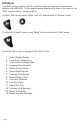
Available Functions for Display in MG2000 Tachometer Screens The functions listed below can be displayed in the user configurable screens. All of the functions may not be available in your installation. If a function is selected for display and that function does not appear on the screen, the function does not exist in this installation. 1. 2. 3. 4. 5. 6. 7. 8. 9. 10. 11. 12. 13. 14. 15. 16. 17. 18. 19. 20. 21. 22.
This page left blank intentionally.
Alarm Mode The “Alarm” screen appears only if an alarm condition exists. The alarm condition may be a warning sent from the engine ECU or a “local” alarm such as “Low Fuel”. When an alarm condition occurs, the “Alarm Screen” will appear and the screens described below will be displayed. The descriptions below also explain how to temporarily override the alarm screen and audible / visual warnings and return to “Normal” mode.
1 Depth 2 Deep 3 ! Any engine alarm except “Engine Emergency Stop” 1 CHECK Red LED blinks. 2 ENGINE Horn “beeps.” (PGN 127489 Field 11 Bits 0-14) 3 ! “Engine Emergency Stop” alarm. 1 ENGINE Red LED on continuously. 2 EMERGENCY Horn on continuously. (PGN 127489 Field 11 Bits 15) 3 STOP ! 1 CHECK 2 ENGINE 3 ! 1 HIGH 2 ENGINE 3 TEMP 1 LOW 2 OIL 3 PRESSURE DEPTH DEEP Displays “Depth Deep” warning. Red LED blinks. Horn “beeps.
LOW OIL LEVEL (PGN 127489 Field 11 Bits 3) LOW FUEL PRESSURE (PGN 127489 Field 11 Bits 4) LOW SYSTEM VOLTAGE (PGN 127489 Field 11 Bits 5) LOW COOLANT LEVEL (PGN 127489 Field 11 Bits 6) WATER FLOW (PGN 127489 Field 11 Bits 7) WATER IN FUEL (PGN 127489 Field 11 Bits 8) CHARGE INDICATOR (PGN 127489 Field 11 Bits 9) PREHEAT INDICATOR (PGN 127489 Field 11 Bits 10) HIGH BOOST PRESSURE (PGN 127489 Field 11 Bits 11) 1 LOW 2 OIL 3 LEVEL 1 LOW 2 FUEL 3 PRESSURE 1 LOW 2 SYSTEM 3 VOLTAGE 1 L
REV LIMIT EXCEEDED (PGN 127489 Field 11 Bits 12) EGR SYSTEM (PGN 127489 Field 11 Bits 13) 1 REV 2 LIMIT 3 EXCEEDED 1 EGR 2 SYSTEM 3 THROTTLE POSITION SENSOR (PGN 127489 Field 11 Bits 14) ENGINE EMERGENCY STOP (PGN 127489 Field 11 Bits 15) Page 31 1 THROTTLE 2 POSITION 3 SENSOR 1 ENGINE 2 EMERGENCY 3 STOP !
Deutsch 12 Pin Connector Pin (For reference only: See drawing HN0389 for details of harness) Function HN0389 Wire Color 1 Power Out to Faria Bus Instruments Red 2 Faria Bus Signal A-Y White 3 Green 5 Faria Bus Signal B-Z Ground In (and ground to Faria Bus Instruments) Power In (+14 V from Ignition) Violet 6 Fuel Sender In Pink 7 Trim Sender In Blue / White 8 NMEA CAN Power Ground Black 9 NMEA CAN Power Red (Micro-C cable) 10 NMEA CAN Shield (if present) Shld (Micro-C cable) 11
This page left blank intentionally.
NMEA 2000 MG2000 Tachometer NMEA2000 PGN’s Supported PGN Field # Bytes 127488 1 1 Bits PGN Name Faria Function Engine Parameter Rapid Update Engine Instance 127488 2 2,3 Engine Parameter Rapid Update RPM 127488 3 4,5 Engine Parameter Rapid Update Boost Pressure 127488 4 6 Engine Parameter Rapid Update Trim 127489 1 1 Engine Parameter Dynamic Engine Instance 127489 2 2,3 Engine Parameter Dynamic Oil Pressure 127489 4 6,7 Engine Parameter Dynamic Engine Temperature 127489
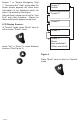
NMEA 2000 Harness HN0389 NMEA2000 Tachometer Cable MG2000 Tachometer 4 5 6 1 2 3 4 5 6 3 2 1 12 11 10 9 8 7 12- pin connector Red White Green Black Violet Pink Blue/ White Black Red Shield White Blue 12 3 4 4- pin connector Red White Green Black & Sheild Heat Shrink Tubing Heat Shrink Tubing 2 1 3 4 5 Black Pin A Pin B Pin C Pin D 5 6 7 8 9 10 11 12 Violet Pink Blue/White Pin 1 Pin 2 Pin 3 Pin 4 Pin 5 Pin 6 Pin 7 Pin 8 Pin 9 Pin 10 Pin 11 Pin 12 Micro-C Cable Pin 1 Pin 2
Harness HN0389 Speedometer Cable MG2000 Speedometer 4 5 6 1 2 3 4 5 6 3 2 1 12 11 10 9 8 7 12- pin connector Pin 1 Pin 2 Pin 3 Pin 4 Pin 5 Pin 6 Pin 7 Pin 8 Pin 9 Pin 10 Pin 11 Pin 12 Red White Green Black Not Used Tan/ Black Tan Not Used Not Used Not Used Not Used Not Used Not Used Not Used Not Used Not Used Not Used Air Temp/ Paddlewheel sender Red (+V) Tan Tan/Black Wire Jacket Not Used 1 2 3 4 5 6 7 8 9 10 11 12 Green (Signal) Bare (Ground) Not Used Not Used White (Thermist
NMEA 2000 Harness HN0401 NMEA 0183 Cable MG2000 Tachometer 4 5 6 11 10 9 8 7 1 12 2 3 6 3 2 5 1 4 6- pin connector Pin 1 Pin 2 Pin 3 Pin 4 Pin 5 Pin 6 Not Used Not Used Red/ White Red/ Blue Not Used Not Used GPS100 Antenna Red/ White Red/ Blue 4 3 Heat Shrink Tubing NMEA 0183-A Red (Ignition) Green (0183-A) Shield (Ground) NMEA 0183-B Not Used Ground *Note: Not Used Not Used Brown* White* Yellow* 1) Cut off the connector at the end of the antenna cable 2) Cut off the followi
Water Pressure Connection NMEA2000 Tachometer NMEA 2000 MG2000 Tachometer From Engine TP1003 Tubing (or equivalent) 4 5 6 1 2 3 4 5 6 3 2 1 12 11 10 9 8 7 Tachometer to 2” Gauge Connection NMEA2000 Tachometer From HN0389 HN0503 4- pin connector Pin A Pin B Pin C Pin D PJ0018 Red White Green Black & Sheild Note: To help reduce moisture in the gauges, be sure to install plug PJ0018 in all open connectors 2" Gauges Page 38
Notes:
Copyright 2006 by the Thomas G. Faria Corporation, Uncasville CT No part of this publication may be reproduced in any form, in an electronic retrieval system or otherwise, without the prior written permission of the company. Faria® is the trademark of the Thomas G.