INSTRUMENTS F Uncasville, CT IA AR C P OR 10 .U NC ASV IL L E , CT MADE IN U. S . 20 A.
Index Description Odometer Trip Odometer Hour-meter Over Speed Condition Maximum Saved Speed Setting the Speedometer Boot menu Service Hours Service Distance Clear Hours Clear Distance Program High Axle Program Low Axle Input Level control for the speed pulse input Run Menu Clear Odometer Set Speed (Over Speed indicator) Calibrate Hi Axle Calibrate Low Axle Harness P1 6 pin connector Harness P2 4 pin connector Page 1 Page 1 Page 1 Page 2 Page 2 Page 3 Page 3 Page 3 Page 4 Page 4 Page 4 Page 4 Page 5 Page 5
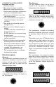
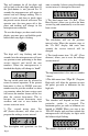
COMMERCIAL SPEEDOMETER Functions available: 1. Odometer display 2. Trip odometer display (resetable) 3. Hour-meter (either rpm or key-on) 4. Service interval for miles or kilometers (reset, clear and disable features) 5. Service interval for hours (reset, clear and disable features) 6. Over-speed indicator (microprocessor output level change at over-speed, resetable) 7. Two speed axle, selected by input to microprocessor. 8. Pulses per mile or kilometer input or change. A.
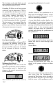
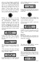
The last digit on the right blinks up and down indicating the hour-meter function. The hour-meter cannot be reset. Grounding P1-E thru an oil low pressure switch can stop the hour-meter. If P1-E is not grounded then the hour-meter will run continuously with the key on. To provide a true engine running hour-meter an external low oil pressure switch is normally used. The low oil pressure switch is closed connecting the pin to ground. The hour meter is not running.
programmed by hand or done automatically, for both of the high and low range axles. Setting the speedometer There are two major speedometer setting routines. If you are in a menu, just do nothing for 32 seconds and the microprocessor will restart and change nothing. The first is activated during boot-up. If the push-button is pressed and held on when power is first turned on the “boot menu” will be activated. 1.
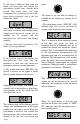
This will continue for all the digits and will go back to the first digit and repeat. If the push-button is not pressed for 32 seconds the microprocessor will return to normal and will change nothing. This is useful if you’re only here to check when the present service interval will occur. The operator may also turn power off at this point and nothing will change in the microprocessor controller. same as number 1 above except the mileage service interval is changed or observed. 3.
pulses per mile or kilometer rounded off to the nearest 100 th. The rightmost digit will be a “P” to remind the operator that they are in the “Programming” mode. The digit changes and inputs are the same as number 1 (Service Hours) above. Also present is the same option to do nothing for 32 seconds and the microprocessor will reset itself and will change nothing.
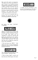
If you want a different item from the menu, you must press and release the push-button before four seconds have passed. The menu items will loop continuously. If you want to get out at this point with no changes, stop at the last menu item “donE”, and in four seconds the microprocessor will return to normal with nothing being changed or if you are in a menu, just do nothing for 32 seconds and the microprocessor will restart and change nothing. 1.
The speed at this point is not important. The operator may even stop and wait, as long as power is not turned off and the measured mile or kilometer is followed as straight as possible, the operator may not turn around and go in the opposite direction. Also for the maximum accuracy, the operator should not enter any off road parking as this would deviate from a straight mile or kilometer measurement.
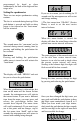
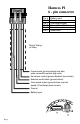
Harness P1 6 - pin connector Pin A Pin B Pin C Pin D Pin E Pin F Battery Input Ground Over speed signal External Push-Button grnd Hourmeter control Speed Axle Shrink Tubing or Wrap 2 speed axle (ground selects low axle, open connection selects high axle) Hourmeter control (ground disables hour-meter) External push button (ground active) Over speed output (ground when over set speed, 20 milliamps max current) Ground Battery input Page 8
Harness P2 4 - pin connector Pin A Pin B Pin C Pin D +8.
Notes:
Copyright 2002 by the Thomas G. Faria Corporation, Uncasville CT No part of this publication may by reproduced in any form, in an electronic retrieval system or otherwise, without the prior written permission of the company.