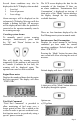
M Serial Bus for Navy Gateway GW0016 Owners’s Manual • Visual/Audible Alert messages • Easy Installation • Waterproof Connections • Easy to read Digital displays • Multiple Interfaces IS0210 rev. A ecr#4821 Aug.
Table of Contents Quick Reference turn system on/off turn on instrument lighting change lighting intensity disable audible alarm in Normal Mode change LCD display reset Trip Fuel Consumed Specifications Turning the Gateway system ON/OFF System description Installation System Operation Tachometer/Fuel Management canceling system alarms engine hour meter total fuel consumed instantaneous fuel consumption trip fuel consumed clear trip fuel consumed fuel remaining fuel remaining alarm setting voltmeter Figure 1
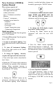
Navy Gateway (GW0016) System Manual intensity is reached no further changes can be made by pressing the “DOWN” button. The system consists of: • One Gateway box to interface with engine and external senders and sensors. • One 4” Tachometer with Fuel Monitor • Various 2” instruments, including but not limited to • Voltmeter • Oil Pressure gauge • Fuel gauge • Engine Temperature gauge • Transmission Temperature Quick operation: 1. To turn on the system: Turn the ignition key to “ON” position. 6.
Gateway System Specifications: Operation voltage: +12 V DC or +24 V DC +12 V DC (10 V DC (Min.) to 16 V DC (max.)) +24 V DC (20 V DC (Min.) to 32 V DC (max.
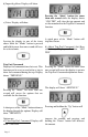
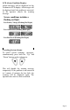
Several alarm conditions may also be displayed in the LCD display when needed: 1 2 3 Low fuel Low oil pressure Low voltage Alarm messages will be displayed on the tachometer LCD display. Messages will also include a flashing red light. All messages will be displayed until either the problem is corrected or the operator manually cancels the warning message. Canceling system alarms To manually cancel system warning messages, simultaneously press both the “Up” and “Down” buttons on the tachometer.
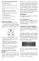
b) Imperial gallons. Display will show c) Liters. Display will show Leaving the display in one of the items above while the “Mode” button is pressed and held for more than one second will save the selected units. Trip Fuel Consumed Displays fuel consumed since last reset. This function can be reset to zero before a trip to show fuel consumed during the trip. Display shows “TRPXXX.X.
Consumed” display) this display will show the decreasing amount of fuel remaining. Holding the “Mode” button for more than one second while the display is showing “ADJXXX.X” will set the amount in the display “XXX.X” into the Trip Fuel Consumed and return to the Trip Fuel Consumed function. The difference between the original and the new amount of fuel will be used to change the calibration of the instant and accumulated fuel data.
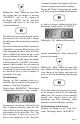
Tachometer Display Sequence When the “Fuel Remaining” reaches this amount, the “Low Fuel” alarm will sound and a warning LED will flash in the display. Quick Press The display will automatically go into “set” mode to allow the operator to reset the alarm value to a lower value to turn off the alarm if desired. If the option is set to zero, the “Low Fuel” alarm will be disabled.
LCD Alarm Condition Displays. Alarm messages will be displayed on the Tachometer LCD display. All messages will be displayed until the problem is corrected, or the operator cancels the warning message. Severe conditions includes a flashing red light. Low Battery Voltage (Flashing Red Light) Low Oil Pressure (Flashing Red Light) Low Fuel Level (Flashing Red Light) Canceling System Alarms To cancel system warnings messages, simultaneously press both the “Up” and “Down” buttons on the tachometer.
Faria® Serial Bus Installation and Wiring Guide The system consists of: • One Gateway box to interface with the engine and external senders and sensors. • One 4” Tachometer with Fuel Monitor • Various 2” instruments, including but not limited to • Voltmeter • Oil Pressure gauge • Engine Temperature gauge • Fuel Level gauge • Transmission Temperature Installation Installation of the Fari® Serial Bus system is accomplished as follows: Gateway Box The Gateway™ box is the central unit of the system.
Appendix 1. Installation and Wiring Table1 Connector Contacts P1 2 P2 4 Pin Pin Function Wire Color Not used 1 Battery Positive (always on)* 2 Ground 3 Switched Power from Ignition Red Purple switch circuit P3 4 4 Ground Black All Faria® Bus Data and N/A Instrument Power P4 2 Not Used (PJ0015) P5 3 Not Used (PJ0016) P6 3 Not Used P7 3 Not Used P8 PP Not Used P9 PP Not Used P10 PP Not Used P11 12 P12 12 P13 2 P14 6 P15 3 Navigation Lights Input Dk.
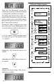
Faria Serial Bus Gateway Typical Power Connections Figure 2 P13 P7 P12 P15 P5 P4 P1 P11 P14 P10 P8 P6 P3 2 1 3 P2 4 Black Red Purple - SOP GEN + Battery Typical Instrument Connections Figure 3 PJ0018 Note: To help reduce moisture in the gauges be sure to install plug PJ0018 in all open connectors.
Faria Serial Bus Gateway Figure 4 Miscellaneous Connections Tachometer Input 6 7 5 8 P 4 9 1210 3P12 2 11 1 12 P13 P15 3 P 4 2 5 1 14 6 6 7 5 8 P 4 9 3 11 10 2 11 1 12 P7 P10 P8 P5 P6 P4 P1 P3 P2 Dk. Blue Pink Lt. Blue Fuel Tank Sender White Oil Pressure Sender Nav. Light Switch White Trans. Sender Instrument Backlight Control Engine Temp.
Copyright 2004 by the Thomas G. Faria Corporation, Uncasville CT No part of this publication may be reproduced in any form, in an electronic retrieval system or otherwise, without the prior written permission of the company. Faria® is the trademark of the Thomas G.