Pro-LX Laminating Card Printer/Encoder User Guide (Rev. 4.
RESTRICTED USE ONLY Fargo Electronics, Inc. Pro-LX Laminating Card Printer/Encoder User Guide (Rev. 4.0), property of FARGO Electronics, Incorporated Copyright 2002, 2003, 2004, 2005, 2006 by FARGO Electronics, Incorporated. All rights reserved. Printed in the United States of America.
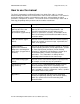
RESTRICTED USE ONLY Fargo Electronics, Inc. How to use the manual The Pro-LX Laminating Card Printer/Encoder User Guide (Rev. 4.0) is, in fact, the troubleshooting and field service manual for the entire Pro-LX Card Printer. The manual is designed to provide installers and technicians with quick, efficient lookup of related procedures, components, and terms. The manual can be used effectively in either soft or hard copy, depending on the preference of the installer or technician.
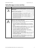
RESTRICTED USE ONLY Fargo Electronics, Inc. Safety Messages (review carefully) Symbol Critical Instructions for Safety purposes Danger: Failure to follow these installation guidelines can result in death or serious injury. Information that raises potential safety issues is indicated by a warning symbol (as shown to the below). Caution: To prevent personal injury, refer to the following safety messages before performing an operation preceded by this symbol.
RESTRICTED USE ONLY Fargo Electronics, Inc.
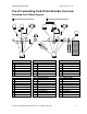
RESTRICTED USE ONLY Fargo Electronics, Inc. Reviewing Pro-LX Boot Up Sequence Step Process 1 On Power up, print and the Lam Stepper Motor engage. 2 Print and Lamination Headlift Sensor checks for current open/closed state. If either Sensor registers closed, the appropriate Headlift Motor engages until Headlift Sensor detects open state. 3 Check SmartCard and Mag Sensors for presence of card.
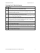
RESTRICTED USE ONLY Fargo Electronics, Inc. Reviewing Pro-LX Sequence of Operations The following sequence describes a dual sided full color print job with magnetic encoding and single sided Lamination. Step Process 1 The File information is received from the PC 2 The Printer checks the installed Ribbon type stored in memory against the Ribbon type command that was sent from the printer. a. If Ribbon type does not match, a Wrong Ribbon Error is displayed on the LCD.
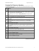
RESTRICTED USE ONLY Fargo Electronics, Inc. Reviewing Pro-LX Sequence of Operations (continued) Step Process 15 The Print Cover Sensor checks for a closed state. 16 The Ribbon Drive Motor engages. 17 The Image Data is burned by the printhead until image data is depleted. All Stop. 18 The Thermistor engages Printhead Cooling Fan to maintain proper operating temperature. 19 The Headlift Motor engages. 20 The Print Headlift Sensor detects an open state. 21 The Print Headlift Motor disengages.
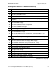
RESTRICTED USE ONLY Fargo Electronics, Inc. Reviewing Pro-LX Sequence of Operations (continued) Step Process 34 The card is fed past the Print TOF Sensor. All Stop. 35 The Flipper Table Clutch engages. 36 The Lamination Stepper engages. 37 The Flipper table rotates to level. All Stop. 38 Repeat steps 10 through 18 for appropriate number of color/overlay panels. 39 The Print and Lamination drive Stepper Motors engage. 40 The Lamination Card Sensor detects presence of card. All Stop.
RESTRICTED USE ONLY Fargo Electronics, Inc. Reviewing Pro-LX Sequence of Operations (continued) Step Process 54 The Flipper Clutch engages. 55 The Flipper table returns to level. 56 The Flipper Clutch disengages. 57 The Card feeds back to Print TOF Sensor then forward to the Lamination card Sensor. All Stop. 58 The Laminate Ribbon Drive activates until Laminate Ribbon Sensor detects patch mark.
RESTRICTED USE ONLY Fargo Electronics, Inc.
RESTRICTED USE ONLY Fargo Electronics, Inc.
RESTRICTED USE ONLY Fargo Electronics, Inc.
RESTRICTED USE ONLY Fargo Electronics, Inc.
RESTRICTED USE ONLY Fargo Electronics, Inc. Section 1: Specifications The purpose of this section is to provide the User with specific information on the Regulatory Compliances, Agency Listings, Technical Specifications and Functional Specifications for the Pro-LX Laminating Card Printer/Encoder (Rev. 3.0). Regulatory Compliances Term Description CSA The Printer manufacturer has been authorized by UL to represent the Card Printer as CSA Certified under CSA Standard 22.2.
RESTRICTED USE ONLY Fargo Electronics, Inc. Agency Listings Term Description Emissions Standards CE, FCC, CRC c1374, BSMI, ITS (EN 55022 Class B:1995, FCC Class B, EN 82082-1:1997). Safety Standards UL 1950, CSA C2.2 No.950-95 and TüV-GS (EN 60950 A1-A4, A11). Technical Specifications Term Description Accepted Standard Card Size CR-80: 3.375 in. x 2.125 in. (85.6mm x 54mm) Accepted Card Thickness .020 in. (20 mil) to .040 in. (40 mil) (.508mm to 1.02mm).
RESTRICTED USE ONLY Fargo Electronics, Inc. Technical Specifications (continued) Term Overlaminate Options Description Thermal Transfer Overlaminate, .25 mil thick, 500 prints PolyGuard Overlaminate, .6 mil thick, 250 prints PolyGuard Overlaminate, 1.
RESTRICTED USE ONLY Fargo Electronics, Inc.
RESTRICTED USE ONLY Fargo Electronics, Inc. Functional Specifications The Card Printer utilizes two different, yet closely related printing technologies to achieve its remarkable direct-to-card print quality for dye-sublimation and resin thermal transfer. (Note: The Card Printer will print from any IBM-PC® or compatible running Windows® 95/98/ME, Windows NT 4.0, Windows 2000 or Windows XP.
RESTRICTED USE ONLY Fargo Electronics, Inc. Printer Components: Top Cover to Power Port Component Description Print Top Cover Opens to allow access to the Printhead, Print Ribbon and card path. (Note: This cover must be closed in order for the Printer to begin printing.) Lamination Top Cover Opens to allow access to the lamination roller, overlaminate and card path. (Note: This cover must be closed in order for the Printer to begin printing.) Cover Release Buttons Unlatches the Top Covers.
RESTRICTED USE ONLY Fargo Electronics, Inc. Printer Components: Top Cover to Power Port (continued) This table displays Printer components. Refer to the table in this section.
RESTRICTED USE ONLY Fargo Electronics, Inc. Printer Components: Top Cover to Power Port (continued) Component Description Ready LED Light When ON, this light indicates the Printer is ready for operation. When OFF, this light indicates the Printer is either OFF or paused and will not operate. If this light is flashing, a Printer error has occurred. (Note: Refer to the Printer's LCD display for the specific type of error that occurred.
RESTRICTED USE ONLY Fargo Electronics, Inc. Printer Components: Top Cover to Power Port (continued) Component Description Card Thickness Adjustment Slide Adjusts the Printer to feed varying card thicknesses. See the Resolving the Card Feeding Errors procedure in Section 2, page 46. Card Output Hopper Stores printed cards; up to 100, 30 mil cards. Rejection Card Hopper Stores cards that have not printed or encoded properly.
RESTRICTED USE ONLY Fargo Electronics, Inc. Printer Components: Centronics-Type Parallel Interface The Card Printer is equipped with a standard 8-bit centronics-type parallel interface port. This communication port is the means through which the Printer receives data from the computer. This section describes the pin assignments and signal specifications for this port.
RESTRICTED USE ONLY Fargo Electronics, Inc. Printer Components: Print Ribbons The Card Printer utilizes both dye-sublimation and/or resin thermal transfer methods to print images directly onto blank cards. Since the dye-sublimation and the resin thermal transfer print methods each provide their own unique benefits, Print Ribbons are available in resinonly, dye-sublimation-only and combination dye-sublimation/resin versions.
RESTRICTED USE ONLY Fargo Electronics, Inc. Printer Components: Resin-Only Print Ribbons Resin-only Print Ribbons consist of a continuous roll of a single resin color. No protective overlay panel (O) is provided since resin images do not require the protection of such an overlay. Type Description Standard Resin Black (K) (provides 1,000 prints) This ribbon provides high resin durability ideal for most general purpose monochrome ID card applications.
RESTRICTED USE ONLY Fargo Electronics, Inc. Printer Components: Dye-Sublimation-Only Print Ribbons A dye-sublimation-only Print Ribbon is available in a monochrome version. This ribbon consists of dye-sublimation ribbon panels which alternate with a clear protective overlay (O) panel. Dye-Sublimation images must have an overlay panel applied to them or they will quickly begin to wear or fade.
RESTRICTED USE ONLY Fargo Electronics, Inc. Printer Components: Dye-Sublimation-Only Print Ribbons (continued) Type Description Full-Color (YMCKO) This ribbon is used to print full-color photo ID cards along with resin black text and bar codes. Both infrared and visible-light bar code scanners can read bar codes printed with resin black. (provides 250 prints) Full-Color (YMCKOK) (provides 250 prints) An overlay panel (O) is included to protect the full-color dye-sublimation printing.
RESTRICTED USE ONLY Fargo Electronics, Inc. Printer Components: Blank Cards Caution: Never run cards with a contaminated, dull or uneven surface through the Printer. Printing onto such cards will ultimately lead to poor print quality and will greatly reduce the life of the Printhead. Always store the card stock in its original packaging or in a clean, dust-free container. Do not print onto cards that have been dropped or soiled.
RESTRICTED USE ONLY Fargo Electronics, Inc. Printer Components: Laminator Danger: The Printer’s Lamination Roller can reach temperatures exceeding 350 degree F (175° C). Use extreme caution when operating the Laminator. Never touch the Lamination Roller unless the Printer Power has been turned off for at least 20 to 30 minutes. Type Description Controls Both the Printer itself and the Printer’s software driver control the built-in laminator.
RESTRICTED USE ONLY Fargo Electronics, Inc. Reviewing the upgraded 81754 PVC Cards The upgraded 81754 PVC cards are designed for a sharper card image quality and for reduced debris and defects on Fargo Card Printers. Carefully read these detailed notes and instructions before applying this information to your Fargo printer or printers. Technician Note 1: The new card lot number starts at Lot # 2010104 with date codes that started on 04/01/2003.
RESTRICTED USE ONLY Fargo Electronics, Inc. Reviewing the upgraded 81754 PVC Cards (continued) Follow these two (2) instructions below: 1. Instruction for new 81754 PVC card stock: Increase the Printer Driver’s Dye-Sub Intensity to print with the new 81754 PVC card stock on Fargo Card Printers (S/N A319 and older). See the chart provided below. See the appropriate Fargo service documents for specific Printer Driver instructions.
RESTRICTED USE ONLY Fargo Electronics, Inc. Printer Components: Laminator The Printer's internal lamination system is used to choose between both a Thermal Transfer Film overlaminate and a polyester patch overlaminate called PolyGuard™. The Thermal Film overlaminate is a relatively thin material that covers a card edge-to-edge and provides a medium level of ID card durability and security.
RESTRICTED USE ONLY Fargo Electronics, Inc. Visual Security Solutions (Specifications) VeriMarkTM Cards - 2-D holographic foil application VeriMarkTM Cards are a low cost, customized 2-D holographic foil application, that is made in two steps. The first step is to emboss a base foil 1.9 cm (L) x 1.3 cm (H) onto the surface of a blank white card. The second step is debossing a custom made dye into the surface of the base foil leaving a customized image, logo or text provided by the customer.
RESTRICTED USE ONLY Fargo Electronics, Inc. Visual Security Card Stock - Tolerances Tolerance of base foil placement will equal +/- .010" from the nearest edges of the card Tolerance of layered foil will equal +/- .010" VeriMarkTM - Application Specifications VeriMarkTM foils will cover a dimensional area of 1.9 cm length x 1.3 cm height.
RESTRICTED USE ONLY Fargo Electronics, Inc. Section 2: General Troubleshooting The purpose of this section is to provide the User with specific procedures relating to the LCD/SmartGuard Messages, Communication Errors, Card Feeding Errors, Print Process Errors, Card Jam Errors, Ribbon Errors, Encoding Errors, Diagnosing Image Problems, Running the Self-Test and Interfacing Information for the Pro-LX Laminating Card Printer/Encoder.
RESTRICTED USE ONLY Fargo Electronics, Inc. Reviewing the Top Line LCD Messages (continued) Message Cause Flipping Card Indicates card is being flipped for backside printing. Head-down Failed Printhead is unable to lower itself. See the Resolving the Headlift Error Message procedure in Section 2, page 49. Head-up Failed Printhead is unable to raise itself. See the Resolving the Headlift Error Message procedure in Section 2, page 49.
RESTRICTED USE ONLY Fargo Electronics, Inc. Reviewing the Top Line LCD Messages (continued) Message Cause Key Card Deleted Indicates the data on the SmartGuard Access Card was successfully deleted. Appears only when using the SmartGuard Security Feature. See the SmartGuard User’s Guide for more information. Lam Error/Out Error Message Indicates a Lam Error/Out Error Message. See Resolving the Lam Error/Out Error Message procedure in Section 2, page 57.
RESTRICTED USE ONLY Fargo Electronics, Inc. Reviewing the Top Line LCD Messages (continued) Message Cause Rasterize Shield Indicates the Printer is loading the SmartShield security image from the SmartGuard Access Card into its memory. Appears when a valid access card containing a SmartShield image is first inserted into the Printer. (Note: If SmartShield image is named, the name will also appear along with this message on the bottom line of the LCD Display.
RESTRICTED USE ONLY Fargo Electronics, Inc. Reviewing the Top Line LCD Messages (continued) Message Cause Smart Card Error Unable to encode smart card. Smart Card Good Indicates smart card was successfully encoded. Smart Encoding Indicates the Printer is writing or encoding data onto the SmartGuard Access Card. Appears only when using the SmartGuard Security Feature. See the SmartGuard User’s Guide for more information.
RESTRICTED USE ONLY Fargo Electronics, Inc. Reviewing the Bottom Line LCD Error / Status Messages (continued) Message Cause Lam Error/Out The overlaminate is either out or an error has occurred. See the Resolving the Lam Error/Out Error Message procedure in Section 2, page 57. Lam Jam/Out Error The overlaminate has either become jammed in the Printer Rollers, stuck to the surface of the card, broken or has run out. See the Resolving the Lam Error/Out Error Message procedure in Section 2, page 57.
RESTRICTED USE ONLY Fargo Electronics, Inc. Reviewing the BOTH Line LCD Error / Status Messages (continued) Message Cause CANCEL=Abort Appears when the Pause/Resume button is pressed any time while the Printer is powered ON. Also appears when the On/Cancel button is pressed during a print job.
RESTRICTED USE ONLY Fargo Electronics, Inc. Communications Errors Resolving the Communication Errors Symptom(s): Incorrect output, communications error on PC or Printer, stalling, no response from Printer, no job printed, “paper out” error.
RESTRICTED USE ONLY Fargo Electronics, Inc. Resolving the Communication Errors (continued) Step 4 Procedure Determine if there is interference from an external device. a. Do not use an A/B switch box or other peripheral in line with the parallel cable. b. If using a switch box or other peripheral, remove it while testing communication between the computer and the Printer. c.
RESTRICTED USE ONLY Fargo Electronics, Inc. Resolving the Communication Errors (continued) Step 7 Procedure Determine whether there is an adequate or inadequate hard drive space. Caution: A large volume of temporary files on the computer can cause communications errors. Access the temporary files by following this process: Search for all folders called TEMP. Once found, clear out the contents of the folders.
RESTRICTED USE ONLY Fargo Electronics, Inc. Card Feeding Errors Resolving the Card Feeding Errors Symptom: Two or more cards feed at the same time or the cards will not feed at all. Step 1 Procedure Clean the Input Roller. a. Open the Printer's top covers and remove all cards, Print Ribbons and overlaminate from the Printer. b. Leave the Printer power ON and the top covers open throughout this procedure. (Note: The card cleaning cartridge can also remain within the Printer during this cleaning process.
RESTRICTED USE ONLY Fargo Electronics, Inc. Resolving the Card Feeding Errors (continued) Step 2 Procedure Ensure the Card Thickness Slide is set correctly. a. Loosen the Slide Lock by rotating it counter clockwise and then push the Card Thickness Slide forward or backward to the appropriate setting. b. With any of the Card Thickness settings, move the slide slightly toward a higher setting until the cards begin feeding (if the Printer seems unable to feed cards at the selected setting). c.
RESTRICTED USE ONLY Fargo Electronics, Inc. Resolving the Flipper Jam Error Message Symptom: A Flipper Jam error is displayed on the LCD. Step 1 Procedure Check for any obstruction. a. Open the lamination top cover. Manually rotate the Flipper Table at a full 360-degrees rotation. b. Visually ensure that there is no obstruction in the path of the Flipper Table’s rotation. 2 Verify the flipper clutch operation. a. Unplug the Printer. Open the Top Lamination Cover. b. Reapply power to the Printer.
RESTRICTED USE ONLY Fargo Electronics, Inc. Print Process Errors Resolving the Headlift Error Message Symptom: The Head Up/Down Error or Roller Up/Down Error is displayed on the LCD. Step 1 Procedure Cycle the headlift motors. a. Remove the front cover. b. Open both the Lamination and the Print Covers. c. Press both buttons on the front control panel at the same time. d. Verify that the Headlift Motors are cycling by watching the Sensor flag rotate through the Sensor. e.
RESTRICTED USE ONLY Fargo Electronics, Inc. Resolving the Cover Open Error Message Symptom: A Cover Open error is displayed when the cover is closed or the Rollers do not operate (when the cover is open). Step 1 Procedure Test the Sensor by following these steps. a. Remove the Rear Cover. b. Use a Digital Voltmeter to: Attach the negative lead to ground. Attach the positive lead to Pin 2 of J11 to test the Print Cover Sensor operation. c.
RESTRICTED USE ONLY Fargo Electronics, Inc. Resolving the Blank Output issues Symptom: A card is ejected blank (that should be printed). Step 1 Procedure Run a self-test. a. Clear any card jams. b. Unplug power from the Printer. c. While holding down the Pause / Resume button, reapply power. d. Release the Pause / Resume button once the Self-test has begun. e. A self-test card will be printed. 2 Look for an image on the ribbon. a. After a self-test has been run, open the top cover. b.
RESTRICTED USE ONLY Fargo Electronics, Inc. Resolving the Blank Output issues (continued) Step 4 Procedure Check the Printhead connections. a. Open the top print cover. b. Remove the two (2) thumbscrews from the Printhead cover plate and remove the cover plate. c. Check to ensure that Power and Data Cables (that connect to the Printhead) are properly seated. d. Remove the Back Cover. e. Ensure that the Printhead Power Cable is properly seated on J15 on the main board. f.
RESTRICTED USE ONLY Fargo Electronics, Inc. Card Jam Errors Resolving the Card Jam: Print Error Message Symptoms: The card is physically jammed in the Printer or a Card Sensor is reporting a card is present. Step 1 Procedure Look for a jammed card in the Printer. a. Open the Printer’s top cover. b. Remove the ribbon from the Printer. c. Check to see if a card is jammed in the print station of the Printer. d.
RESTRICTED USE ONLY Fargo Electronics, Inc. Resolving the Card Jam: Mag Error / Smart Error Message Symptoms: The Card Jam: Mag Error or Card Jam: Smart Error is displayed on the LCD. Step 1 Procedure Look for a jammed card in the Printer. a. Open the Printer’s top cover. b. Remove the ribbon from the Printer. c. Check to see if a card is jammed in the print station of the Printer. d.
RESTRICTED USE ONLY Fargo Electronics, Inc. Resolving the Card Jam: Lam Error Message Symptom: The Card Jam: Lam Error is displayed on the LCD. Step 1 Procedure Look for a jammed card in the Printer. a. Open the Printer’s top cover. b. Remove the ribbon from the Printer. c. Check to see if a card is jammed in the Lam Station of the Printer. d. If a card is jammed in the Printer, use the Pause / Resume button and the On / Cancel buttons to move the feed Rollers and free the card.
RESTRICTED USE ONLY Fargo Electronics, Inc. Resolving the Card Jam: Flip Error Message Symptom: A Card Jam: Flip Error is displayed on the LCD. Step 1 Procedure Run a Self test. a. Clear any card jams. b. Unplug power from the Printer. c. While holding down the Pause / Resume button, reapply power. d. Release the Pause / Resume button once the self-test has begun. (Note: A test card will be printed.) e. If successful, this will ensure proper flipper operation on a simple doublesided print.
RESTRICTED USE ONLY Fargo Electronics, Inc. Ribbon Errors Resolving the Lam Error/Out Error Message Symptom: The Printer seems to skip PolyGuard overlaminate patches or simply wind the overlaminate until the Printer's Ready LED flashes. Step 1 Procedure Check that the proper Over-Laminate type is installed according to the Lamination Type option selected in the Printer Driver. a. Open the Printer control panel from the Computer.
RESTRICTED USE ONLY Fargo Electronics, Inc. Resolving the Lam Error/Out Error Message (continued) Step 3 Procedure Check the Laminate Ribbon Clutch to determine if it is too loose. a. Remove the back cover. b. Use a 7/16” wrench to tighten the nut on the end of the encoder wheel by ½ - turn. 4 Test the Encoder Sensor. a. Remove the back cover. b. Using a Digital voltmeter, connect the negative lead to ground. c. Connect the positive lead to Pin 4 of J13. If blocked, the voltage should read 4.
RESTRICTED USE ONLY Fargo Electronics, Inc. Resolving the Skipping Ribbon Panel issues Symptom: The Printer is using more than one set of ribbon panels to print one side of a card. Step 1 Procedure Calibrate the Ribbon Sensor. a. Reset the Printer to clear any Error Messages by removing Power and reapplying. b. Open the Printer Control Panel from the Computer. If using Windows 95/98/ME, right click on the Pro-LX Card Printer Icon and select Properties. If using Windows NT 4.
RESTRICTED USE ONLY Fargo Electronics, Inc. Resolving the Skipping Ribbon Panel issues (continued) Refer to the previous procedure. Continued on the next page Pro-LX Laminating Card Printer/Encoder User Guide (Rev. 5.
RESTRICTED USE ONLY Fargo Electronics, Inc. Resolving the Skipping Ribbon Panel issues (continued) Step 2 Procedure Adjust the Ribbon Clutch a. Remove the back cover. b. Use a 7/16th wrench to tighten the nut on the end of the encoder wheel by a ½ - turn. 3 Test the Encoder Sensor. a. Remove the back cover. b. Using a Digital Voltmeter, connect the negative lead to ground. c. Connect the positive lead to Pin 4 of J13. If blocked, the voltage should read 4.9 to 5.5 volts DC.
RESTRICTED USE ONLY Fargo Electronics, Inc. Resolving the Wrong Ribbon error (being displayed incorrectly) Symptom: A Wrong Ribbon Error is displayed on the LCD even though the correct ribbon is installed in the Printer. Step 1 Procedure Verify the driver settings are correct. a. Open the Printer Control Panel from the Computer. If using Windows 95/98/ME, right click on the Pro-LX Card Printer Icon and select Properties. If using Windows NT 4.
RESTRICTED USE ONLY Fargo Electronics, Inc. Resolving the Wrong Ribbon error (being displayed incorrectly) (continued) Step 2 Procedure Test the Ribbon ID Sensor. a. Unplug the Printer. b. Remove the back cover. c. Flip switches 3 and 4 on the bank of DIP switches in the Main Board corner. d. With the top covers closed, apply power to the Printer while holding down the Pause/Resume button. e. Once the LCD screen displays RUNNING SELF TEST #12, release the Pause/Resume Button. f.
RESTRICTED USE ONLY Fargo Electronics, Inc. Resolving the Ribbon Breaking issues Symptom: The Ribbon breaks when printing or a Ribbon Jam Error is displayed on the LCD Step 1 Procedure Calibrate the Ribbon Sensor. a. Reset the Printer to clear any Error Messages by removing Power and reapplying. b. From the Computer, open the Printer control panel. If using Windows 95/98/ME, right click on the Pro-LX Card Printer Icon and select Properties. If using Windows NT 4.
RESTRICTED USE ONLY Fargo Electronics, Inc. Resolving the Ribbon Breaking issues (continued) Step 2 Procedure Determine where the ribbon is breaking. a. Open the Top Print Cover. b. Remove the ribbon from the Printer. c. Inspect the ribbon at the break point. 3 If the Ribbon broke before any print was applied to the card, continue to Step 3. If the Ribbon broke after applying the print to the card, continue to Step 4. Adjust the Image Placement. a.
RESTRICTED USE ONLY Fargo Electronics, Inc. Resolving the Ribbon Breaking issues (continued) Step 4 Procedure Adjust the Image Placement. a. Reset the Printer to clear any Error Messages by removing Power and reapplying. b. Open the Printer Control Panel from the Computer. If using Windows 95/98/ME, right click on the Pro-LX Card Printer Icon and select Properties. If using Windows NT 4.0, right click on the Pro-LX Card Printer and select Document Defaults.
RESTRICTED USE ONLY Fargo Electronics, Inc. Resolving the Lamination (not adhering to the card surface) problem Symptom: The lamination will not transfer to the card or is easily peeled off the card. Step 1 Procedure Ensure the Card quality by verifying that these requirements are met: a. Requirement 1: That the Printer does print onto any card with a clean, level and polished PVC surface.
RESTRICTED USE ONLY Fargo Electronics, Inc. Resolving the lamination (not adhering to the card surface) problem (cont.) Step 2 Procedure Check Lamination Temperature. a. Open the Printer Control Panel from the Computer. If using Windows 95/98/ME, right click on the Pro-LX Card Printer Icon and select Properties. If using Windows NT 4.0, right click on the Pro-LX Card Printer and select Document Defaults.
RESTRICTED USE ONLY Fargo Electronics, Inc. Encoding Errors Resolving the Mag Verify Error Message Symptoms: A Mag Verify error is displayed on the LCD when attempting to encode. Step Procedure 1 Check to ensure that the cards are loaded with the Magnetic Stripe facing down and towards the back of the Printer. 2 Verify the Driver settings if cards are loaded properly. Properly loaded cards will be oriented with the mag stripe facing down and toward the back of the Printer.
RESTRICTED USE ONLY Fargo Electronics, Inc. Resolving the Mag Verify Error Message (Continued) Refer to the previous procedure regarding this display. 0.293inches(nul characters) Start Sentinel Position Magnetic Head (3 Stationary Magnetic Tracks) Direction of Card Travel whilebeing Magnetically Encoded Card Feed Path Encoding Module Flipper Table Flip Sensor Card Feed Roller C be R-8 en gin 0 c co ni ard di ng a ng o t t pa f th he ss e .
RESTRICTED USE ONLY Fargo Electronics, Inc. Determining why the Printer cannot read encoded data Step Procedure 1 Verify that the cards are loaded properly with the Magnetic Stripe facing down and towards the back of the Printer. 2 Verify that the card is encoded with magnetic data by using a Magnetic Imager or Developer Solution. 3 Use WordPad (a Windows 95/ 98/ ME/ NT/ 2000/XP word processing program in the Accessories Program Group). a. Go to the File menu and select Page Setup. b.
RESTRICTED USE ONLY Fargo Electronics, Inc. Resolving data intended for the Magnetic Stripe (being printed on the card) problem Step Procedure 1 Confirm that the application is formatting the magnetic string correctly. See the Using the Magnetic Track Selection option procedure in Section 3, page 121. 2 a. Use WordPad (a Windows 95/ 98/ ME/ NT/ 2000/XP word processing program in the Accessories Program Group). b. Go to the File menu and select Page Setup. c.
RESTRICTED USE ONLY Fargo Electronics, Inc. Diagnosing Image Problems Resolving the Pixel Failure problems Symptom: A thin line or scratch travels the entire length of the card. Step Procedure 1 Check the card stock for scratches. Replace the cards (as needed). 2 Examine the Printhead for visible damage. 3 Clean the Printhead. See Cleaning the Printhead procedure in Section 4, page 186. 4 Replace the Cleaning Tape. See Replacing the Cleaning Tape procedure in Section 4, page 189.
RESTRICTED USE ONLY Fargo Electronics, Inc. Resolving the Card Surface Debris problems Symptom: Prints have spots (white or colored voids) and/or dust on them. Step Procedure 1 Be sure the cards are clean and stored in a dust-free environment. Do not use cards with embedded contaminants in the surface. 2 Clean the inside of the Printer. See Cleaning the Printer’s Interior procedure in Section 4, page 192. 3 Replace the Cleaning Tape. See Replacing the Cleaning Tape procedure in Section 4, page 189.
RESTRICTED USE ONLY Fargo Electronics, Inc. Resolving the Incorrect Image Darkness problems Symptom: Printed cards are too dark or too light. Step Procedure 1 Run a self-test to identify problems with the driver settings. See Running the Self Test in Section 2, page 87. 2 Adjust the Dye-Sub Intensity setting within the Image Color tab of the Printer Driver. See Using the Image Color tab procedure in Section 3, page 157.
RESTRICTED USE ONLY Fargo Electronics, Inc. Resolving the Incorrect Image Darkness problems (continued) Step 3 Procedure Correct the Image Darkness. See Using the Image Darkness option in Section 3, page 100. Pro-LX Laminating Card Printer/Encoder User Guide (Rev. 5.
RESTRICTED USE ONLY Fargo Electronics, Inc. Resolving the Ribbon Wrinkle problems Symptom: Printed cards have off-colored lines or streaks on them. Step Procedure 1 Confirm that the Printer is using the most current driver via: http://www.fargo.com 2 Reduce the Dye-Sub Intensity setting within the Image Color tab of the Printer Driver. See Using the Image Color tab procedure in Section 3, page 157. Continued on the next page Pro-LX Laminating Card Printer/Encoder User Guide (Rev. 5.
RESTRICTED USE ONLY Fargo Electronics, Inc. Resolving the Ribbon Wrinkle problems (continued) Step Procedure 3 Reduce the Image Darkness. See Using the Image Darkness option in Section 3, page 100. 4 Increase the Ribbon tension. a. Unplug the Printer. b. Remove the rear cover. c. Use a 7/16th wrench to tighten the nut on the Ribbon Encoder ½ - turn. d. Reapply power. e. Print a card. If the wrinkle effect is gone, continue printing.
RESTRICTED USE ONLY Fargo Electronics, Inc. Resolving the Excessive Resin Printing problems Symptom: Black resin text and barcodes appear smeared or too thick. Step 1 Procedure Reduce the Resin Heat setting within the Image Color tab of the Printer Driver. See Using the Image Color tab procedure in Section 3, page 157. Continued on the next page Pro-LX Laminating Card Printer/Encoder User Guide (Rev. 5.
RESTRICTED USE ONLY Fargo Electronics, Inc. Resolving the Excessive Resin Printing problems (continued) Step 2 Procedure Reduce the Image Darkness. See Using the Image Darkness option in Section 3, page 100. Pro-LX Laminating Card Printer/Encoder User Guide (Rev. 5.
RESTRICTED USE ONLY Fargo Electronics, Inc. Resolving the Incomplete Resin Printing problems Symptom: Black resin text and barcodes appear faded or too light. Step Procedure 1 Increase the Resin Heat setting within the Image Color tab of the Printer Driver. See Using the Image Color tab procedure in Section 3, page 157. 2 Increase the Image Darkness. See Using the Image Darkness option in Section 3, page 100. Pro-LX Laminating Card Printer/Encoder User Guide (Rev. 5.
RESTRICTED USE ONLY Fargo Electronics, Inc. Resolving the Image Placement problems Symptom: Printing is cut off or is not centered on the card or a white border appears. Step 1 Procedure Verify if the Image Position option within the Calibrate tab is set incorrectly. a. Open the Printer Control Panel from the Computer. If using Windows 95/98/ME, right click on the Pro-LX Card Printer Icon and select Properties. If using Windows NT 4.
RESTRICTED USE ONLY Fargo Electronics, Inc. Resolving the Image Placement problems (continued) Refer to the previous procedure. Pro-LX Laminating Card Printer/Encoder User Guide (Rev. 5.
RESTRICTED USE ONLY Fargo Electronics, Inc. Resolving the Image Placement problems (continued) Step 2 Procedure Verify the Image Placement setting is set correctly. a. Open the Printer Control Panel from the Computer. If using Windows 95/98/ME, right click on the Pro-LX Card Printer Icon and select Properties. If using Windows NT 4.0 right click on the Pro-LX Card Printer and select Document Defaults. If using Windows 2000/XP, right click on the Pro-LX Card Printer and select Printing Preferences.
RESTRICTED USE ONLY Fargo Electronics, Inc. Resolving the Image Placement problems (continued) Refer to the previous procedure. Pro-LX Laminating Card Printer/Encoder User Guide (Rev. 5.
RESTRICTED USE ONLY Fargo Electronics, Inc. Resolving the Poor Image Quality problems Symptom: Photos on the cards look pixilated or grainy, as shown below. Step 1 Procedure Use high-resolution, 24-bit color images to capture an image: at a 24-bit color setting, at 300 dpi and at the same size (that it will be printed on the card, as captured either with a scanner or with a digital camera).
RESTRICTED USE ONLY Fargo Electronics, Inc. Running the Self Test Perform a self-test after (a) an initial setup of the Printer, (b) a calibration procedure has been conducted or (c) a part has been replaced to check for proper Printer operation. Step 1 Procedure Verify that a full-color ribbon is installed and that cards are properly loaded. Caution: If the power is ON, disconnect the Power Cable from the Printer’s rear panel. 2 Press and hold the Pause/Resume button.
RESTRICTED USE ONLY Fargo Electronics, Inc. Reviewing the Main Circuit Board Perform the standard self-test and the other test modes (made available by changing the DIP Switch Settings within the Printer). Use these additional self-tests to isolate and diagnose Printer problems and test for proper Printer operation after Printer calibration. (Note: The Main Circuit Board (below) displays the location of the DIP switches and how to activate them.
RESTRICTED USE ONLY Fargo Electronics, Inc. Using the DIP Switch (Self-test) Step 1 Procedure Activate any of these diagnostic tests and Calibration modes. See Running the Self Test in Section 2, page 87. During the activation of the Self-test, the Printer will: Detect the change to the DIP Switch Settings. See Using the DIP Switch Self Test in Section 2, page 89. Operate the Printer in that selected Test or Calibration mode.
RESTRICTED USE ONLY Fargo Electronics, Inc. Using the DIP Switch (continued) Step 4 Procedure When completed, turn OFF the power to the Printer to reset the operating mode of the Printer. The first illustration (below) shows all eight (8) switches in the normal OFF position. The second illustration (below) shows Switches No. 1,2 and 3 in the ON position. (Note: The Ribbon Sensor calibration without the need of a PC).
RESTRICTED USE ONLY Fargo Electronics, Inc. Setting the DIP Switch Settings (Note: The capital letter “X” indicates that the switch should be set to ON or DOWN.) SW1 SW2 SW3 SW4 SW5 SW6 Diagnostic modes Standard Self-test (YMC) front, (K or B) on back X X X Self test with Monochrome Dye-Sub (B) X X Self test with Monochrome Resin (K) X X Ribbon Sensor Calibration (align on clear or yellow panel, PC not required) X 15 Shade self-test (YMC) PolyGuard Lamination will be applied.
RESTRICTED USE ONLY Fargo Electronics, Inc. Running the 15-Shade Self Test This is the Self-test that appears when specific changes are made to the DIP Switch Settings. Pro-LX Laminating Card Printer/Encoder User Guide (Rev. 5.
RESTRICTED USE ONLY Fargo Electronics, Inc. Interfacing Information The Printer is equipped with a standard 8-bit Centronics-type Parallel Data Communications Port. (Note: The Printer's Parallel Interface Connector is a standard 36-pin Amp type with two metal-wire retaining clips. It mates with a standard PC to Printer parallel cable.) Caution: For best results, keep the Interface Cable to less than six (6) feet.
RESTRICTED USE ONLY Fargo Electronics, Inc. Reviewing the Centronics Parallel Pin Assignments Pin No. Signal 1 ______ In Direction Description Strobe A LOW pulse greater than 1 µs causes the Printer to read one byte of data.
RESTRICTED USE ONLY Fargo Electronics, Inc. Reviewing the Centronics Parallel Pin Assignments (continued) Pin No. Signal Direction Description 12 Paper Error Out Low = OK, High = media error 13 Ready Out Low = off-line, High = on-line 14, 15 Not Used 16 Sig Gnd 17 Chassis Gnd 18 HI 19 to 30 Sig Gnd 31 _________ Reset/Input Clean Not Used 32 _____ Out 33 to 36 Not Used Error Low = Printer error, High = OK Not Used Pro-LX Laminating Card Printer/Encoder User Guide (Rev. 5.
RESTRICTED USE ONLY Fargo Electronics, Inc. Reviewing the Printer Timing Diagram The timing diagram (below) illustrates the data and handshake lines during the transfer of one data byte to the Computer. DATA VALID Data 0 - Data 7 Strobe Tdsu Tstr Tdh Busy Tbp Tack Acknlg Pro-LX Laminating Card Printer/Encoder User Guide (Rev. 5.
RESTRICTED USE ONLY Fargo Electronics, Inc. Reviewing the Printer Timing Interval Description Tdsu Data setup time Tstr _____ Data strobe width Minimum Value Typical Value 0.5 µs 1 µs Tack ______ Acknlg pulse width 3.75 µs Tdh Data hold time 0.5 µs Tsb _____ Busy delay time from data strobe 0.5 µs (max.) Pro-LX Laminating Card Printer/Encoder User Guide (Rev. 5.
RESTRICTED USE ONLY Fargo Electronics, Inc. Section 3: Printer Adjustments Review this section for specific information on the Safety Messages and the Printer Driver Options; and the Calibrate, Magnetic Encoding, Lamination, Overlay / Print Area, Image Color, Device Options and Card tabs for the Pro-LX Card Printer. (Note: Procedures and instructions in this Section may require special precautions to ensure the safety of the personnel performing the operations.
RESTRICTED USE ONLY Fargo Electronics, Inc. Using the Settings dialog box Access the Settings dialog box via the Settings button on the Calibrate tab. Use the adjustment mode to change the Printer's internal settings for overall Image Darkness, Image Placement, Print Length, Magnetic Offset, Flipper Offset and Lamination Placement. (Note: The Card Printer is equipped with an internal adjustment mode programmable through the Settings dialog box.
RESTRICTED USE ONLY Fargo Electronics, Inc. Using the Image Darkness option Use this option to set the overall darkness of the printed image by increasing or decreasing the amount of heat used by the Printhead when printing. Step 1 Procedure Lighten the printed image by clicking the down arrow value and decrease the amount of Printhead heat. to enter a negative OR Darken the image by clicking the up arrow increase the amount of Printhead heat.
RESTRICTED USE ONLY Fargo Electronics, Inc. Using the Image Placement option Use this option to adjust the lengthwise or horizontal position of the printed image on a card so it appears centered. (Note: When adjusting this value, keep in mind that cards always remain in the same landscape orientation while moving through the Printer.) The diagram (below) represents how the printed image will move in relation to the fixed card position as a positive or negative Image Placement value is entered.
RESTRICTED USE ONLY Fargo Electronics, Inc. Using the Print Length option Use this option to reduce or lengthen the overall printable area in order to optimize edge-toedge printing toward the trailing edge of a card. (Note: When adjusting this value, keep in mind that cards always remain in the same position while moving through the Printer.) The diagram (below) represents how the print length will move in relation to the fixed card position as a positive or negative Print Length value is entered.
RESTRICTED USE ONLY Fargo Electronics, Inc. Using the Magnetic Offset option Use this option only if the Printer has a built-in Magnetic Stripe encoder. (Note: If so, use this option to shift the starting point of where the Printer will begin encoding the magnetic Track data on a card's Magnetic Stripe. When adjusting this value, keep in mind that a card and its Magnetic Stripe will always remain in the same relative position as the card travels through the Printer.
RESTRICTED USE ONLY Fargo Electronics, Inc. Using the Flipper Offset option Use this option to set the position of the flipper so that it is level with the card path. Step 1 Procedure Lower the lead-in of the Flipper Table (or offset the Flipper more clockwise) by clicking on the down arrow to enter a negative value. OR Raise the lead-in of the Flipper Table (or offset the Flipper more counterclockwise) by clicking the up arrow to enter a positive value.
RESTRICTED USE ONLY Fargo Electronics, Inc. Using the Lamination Placement option Use this option to adjust the lengthwise or horizontal position of a PolyGuard patch on a card so it appears centered. (Note: When adjusting this value, the cards always remain in the same landscape orientation while moving through the Printer.) The diagram (below) represents how the PolyGuard patch will move in relation to the fixed card position as a positive or negative Lamination Placement value is entered.
RESTRICTED USE ONLY Fargo Electronics, Inc. Using the Lamination Placement option (continued) Step Procedure 2 Once adjustment is complete, click the OK button to save the adjustments or click the Cancel button to cancel any adjustments (just made). 3 a. Print a self-test after making adjustments to the Internal Printer settings. (Note: This self-test print helps determine if these settings are set properly.) b.
RESTRICTED USE ONLY Fargo Electronics, Inc. Adjusting the Card Flattener Use the adjustable Card Flattener to fine-tune the flatness of laminated cards. (Note: This flattener works by reverse bending cards as they eject from the laminator while they are still warm.) Step 1 Procedure Verify there is no card warpage. (Note: In most cases, card warpage is only a concern when laminating on a single side of card stock that has a PVC-based core rather than a polyester-based core.
RESTRICTED USE ONLY Fargo Electronics, Inc. Adjusting the Card Flattener (continued) Step 5 Procedure If laminated cards are bowing upward, turn the Card Flattener Adjustment Knob clockwise or one full rotation, then print and laminate a test card. Repeat this process as necessary. (Note: This pushes the flattener roller down to increase the reverse bending pressure.) OR If the card is bowing downward, the reverse bending pressure may be too great.
RESTRICTED USE ONLY Fargo Electronics, Inc. Adjusting the Laminator Adjust the laminator's Card Guide Rail if the PolyGuard patches are being applied too closely to or overlapping a card's top or bottom edge (as the card travels through the Printer. Step Procedure 1 Loosen the two screws that fasten the Card Guide Rail to the Printer's main chassis.
RESTRICTED USE ONLY Fargo Electronics, Inc. Adjusting the Laminator (continued) Step Procedure 3 Move the Card Guide Rail slightly toward the front of the Printer (opposite the direction the patch must move in) if the PolyGuard patch is being placed more toward a card's bottom edge (as shown in the lower display). 4 a. Always make very slight adjustments to the Card Guide Rail and run a test print after each adjustment until the optimum patch position is found. b.
RESTRICTED USE ONLY Fargo Electronics, Inc. Printer Driver Options Access the Pro-LX Card Printer Properties window via Start > Settings > Printers > Pro-LX Card Printer (icon) > Pro-LX Card Printer (which brings up the Pro-LX Card Printer Properties window). Pro-LX Laminating Card Printer/Encoder User Guide (Rev. 5.
RESTRICTED USE ONLY Fargo Electronics, Inc. Using the Calibrate tab Use this option to (a) control the position of the printable area in relation to the card, (b) calibrate Sensors and (c) adjust the internal Printer settings. Pro-LX Laminating Card Printer/Encoder User Guide (Rev. 5.
RESTRICTED USE ONLY Fargo Electronics, Inc. Using Image Position controls Use the Image Position controls to adjust the position of the overall print area to be precisely centered on a card. Step 1 Procedure Click on the Vertical and Horizontal adjustment arrows to adjust the Image Position values. When adjusting these values, keep in mind that cards always remain in the same position while moving through the Printer, regardless of image orientation.
RESTRICTED USE ONLY Fargo Electronics, Inc. Using Image Position controls (continued) Review the Image Position diagram, which displays how the printed image will move in relation to the fixed card position as positive and negative image placement values are entered. Step 2 Procedure Use the Vertical adjustment to move the image: Move toward the rear of the Printer if a positive number is entered. Move toward the front of the Printer if a negative number is entered.
RESTRICTED USE ONLY Fargo Electronics, Inc. Using the Lamination Position control Use the Lamination Position control to adjust the horizontal position of the PolyGuard overlaminate. (Note: This control functions in the exact same fashion as the Image Position controls, except only the horizontal position of the overlaminate requires an adjustment.) Step Procedure 1 Click on the Horizontal Adjustment arrows to adjust the Lamination position.
RESTRICTED USE ONLY Fargo Electronics, Inc. Using the Sensors and Settings buttons Use the Sensors button to bring up a separate dialog box for calibrating the Printer's ribbon and lamination Sensors. Continued on the next page Pro-LX Laminating Card Printer/Encoder User Guide (Rev. 5.
RESTRICTED USE ONLY Fargo Electronics, Inc. Using the Sensors and Settings buttons (continued) Use the Settings button to bring up a separate dialog box for adjusting the internal Printer settings (that are customized for every Printer at the factory and saved directly within the Printer's memory). Pro-LX Laminating Card Printer/Encoder User Guide (Rev. 5.
RESTRICTED USE ONLY Fargo Electronics, Inc. Using the Magnetic Encoding tab Use this option only if the Printer has an optional Magnetic Stripe Encoding Module installed. This Section describes these options and the Printer's magnetic encoding process. Step 1 Procedure Select the Magnetic Encoding tab to display options for controlling the Magnetic Stripe encoding process. Continued on the next page Pro-LX Laminating Card Printer/Encoder User Guide (Rev. 5.
RESTRICTED USE ONLY Fargo Electronics, Inc. Using the Magnetic Encoding tab (continued) Step 2 Procedure Adjust the following Magnetic Encoding options accordingly to change the ISO Standards for Tracks 1, 2 and 3. Pro-LX Laminating Card Printer/Encoder User Guide (Rev. 5.
RESTRICTED USE ONLY Fargo Electronics, Inc. Using the Encoding Mode option Use the Encoding Mode option to specify the desired, magnetic encoding standard. Step 1 Procedure Select the JIS II mode provides encoding compatibility with the JIS C 6220 Type II cards commonly used in Japan. When the JIS II mode is selected, only Track 2 will be encoded. (Note: No encoding customization options are available with the JIS II mode.
RESTRICTED USE ONLY Fargo Electronics, Inc. Using the Coercivity option Use the Coercivity option to select the type of Magnetic Stripe to encode. Step 1 Procedure Select High Co to set the Oersted level to 2750 OR Select Low Co to set the Oersted Level to 300. Using the Magnetic Track Selection option Use the Magnetic Track Selection option to specify which Track to configure through the Magnetic Track Options if the application requires customization of the standard ISO encoding process.
RESTRICTED USE ONLY Fargo Electronics, Inc. Using the Magnetic Track Selection (continued) Step 1 Procedure Select a Track selection to: a. Change all options separately for each of the three individual Tracks. b. Select the Default button for each of the separate Tracks to set these options back to the ISO Standard settings (once they have been changed). (Important: Please refer to the following for a description of all Magnetic Track Options.
RESTRICTED USE ONLY Fargo Electronics, Inc. Reviewing the Enable MLE Support checkbox Multi-Language Extension (MLE) support in Windows XP can cause text strings to be broken up into fragments. This fragmentation of the text string prevents magnetic encoding. Step 1 Procedure Check this box to allow the Driver to process the fragmented text. Pro-LX Laminating Card Printer/Encoder User Guide (Rev. 5.
RESTRICTED USE ONLY Fargo Electronics, Inc. Using the Magnetic Track Options Use the Magnetic Track options for these purposes: Customize the ISO encoded data format for each of the Magnetic Stripe's three Tracks. Customize each Track independently of the other two. Specify which of the three Tracks to customize by selecting one of the three Track options.
RESTRICTED USE ONLY Fargo Electronics, Inc. Using the Bit Density radio buttons Use this option to customize the Bit Recording Density (Bits per Inch) used to encode the magnetic data on the currently selected Track. The default ISO Standard selections for this option are as follows: Step 1 Procedure Select 75 BPI to change the bits per inch to 75 BPI. OR Select 128 BPI to change the bits per inch to 128 BPI. OR Select 210 BPI to change the bits per inch to 210 BPI .
RESTRICTED USE ONLY Fargo Electronics, Inc. Using the ASCII Offset Use this option to customize the Character ASCII Offset used to encode the magnetic data on the currently selected Track. (Note: This character offset value is subtracted from the ASCII value of each Magnetic Stripe data character prior to encoding on the Track.) Step 1 Procedure Select NULL to change the ASCII Offset to NULL. OR Select SPACE to change the ASCII Offset to SPACE. OR Select ZERO to change the ASCII Offset to ZERO.
RESTRICTED USE ONLY Fargo Electronics, Inc. Using the LRC Generation radio buttons Use this option to customize the LRC Generation Mode (used to encode the magnetic data on the currently selected Track). Step 1 Procedure Select NO LRC to change the LRC Generation to none. OR Select Even Parity to change the LRC Generation to Even Parity. OR Select Odd Parity to change the LRC Generation to Odd Parity.
RESTRICTED USE ONLY Fargo Electronics, Inc. Using the Verification radio buttons Use this option to customize the encoding verification settings. Step 1 Procedure Select the Auto Eject 1st Error option to instruct the Printer to verify that all magnetic data has been correctly encoded on each card. (Note: The Auto Eject option is the most direct means of dealing with misverified cards; however, it may be undesirable when dealing with encoding errors.
RESTRICTED USE ONLY Fargo Electronics, Inc. Using the Shift Data Left checkbox Use this option to shift the recorded magnetic data to the left-hand side of the card's Magnetic Stripe. OR Use this option for situations that require cards to be readable with insert type readers that may not be able to read the right-hand side of the card. Step 1 Procedure Select the Shift Data Left option to apply to all Tracks.
RESTRICTED USE ONLY Fargo Electronics, Inc. Reviewing ISO Track Locations Review the magnetic encoding module, which encodes onto Tracks in accordance with an ISO 7811-2 Magnetic Stripe. (Note: Refer to the diagram (below) for Track locations.) 0.223" 0.353" 0.493" TRACK1 0.110" 0.130" TRACK2 0.110" 0.140" TRACK3 0.110" Pro-LX Laminating Card Printer/Encoder User Guide (Rev. 5.
RESTRICTED USE ONLY Fargo Electronics, Inc. Sending Track Information Magnetic Track data is sent in the form of text strings from the application software to the Printer Driver along with all of the other printable objects within the card design. Magnetic Track Data added: In order for the Printer Driver to differentiate between magnetic Track data and the rest of the printable objects, the magnetic Track data strings must be uniquely tagged or added.
RESTRICTED USE ONLY Fargo Electronics, Inc. Reviewing Tracks 1, 2 and 3 (in table format) Review this table, which displays the SS, ES, FS and the valid characters defined for each Track. Track 1 Start Sentinel End Sentinel Field Separator Valid Characters Maximum Number of Characters % ? ^ ASCII 32-95 78 (See the table below.) Track 2 ; ? = ASCII 48-63 39 (See the table below.) Track 3 ; ? = ASCII 48-63 106 (See the table below.
RESTRICTED USE ONLY Fargo Electronics, Inc. Reviewing the ASCII Code and Character Table ASCII Code Character ASCII Code Character ASCII Code Character 32 space 56 8 80 P 33 ! 57 9 81 Q 34 " 58 : 82 R 35 # 59 ; 83 S 36 $ 60 < 84 T 37 % 61 = 85 U 38 & 62 > 86 V 39 ' 63 ? 87 W 40 ( 64 @ 88 X 41 ) 65 A 89 Y 42 * 66 B 90 Z 43 + 67 C 91 [ 44 ' 68 D 92 \ 45 - 69 E 93 ] 46 .
RESTRICTED USE ONLY Fargo Electronics, Inc. Using the Lamination tab Use these options to control the Printer's lamination process. Pro-LX Laminating Card Printer/Encoder User Guide (Rev. 5.
RESTRICTED USE ONLY Fargo Electronics, Inc. Selecting from the Lamination Side dropdown menu Use this option to customize what side(s) of the card the Printer is supposed to laminate. Step 1 Procedure Select the No Lamination option to avoid using the Printer's built-in laminator. OR Select Laminate Front Side, Laminate Back Side or Laminate Both Sides to specify the side(s) of the card to laminate. Pro-LX Laminating Card Printer/Encoder User Guide (Rev. 5.
RESTRICTED USE ONLY Fargo Electronics, Inc. Selecting from the Lamination Type dropdown menu Use the Lamination Type dropdown menu to select the correct option. Step 1 Procedure Select the PolyGuard Lamination for either the 1.0 mil or 0.6 mil thick patch. (Note: These both offer equivalent protection but require different heat settings and lamination speeds.) OR Select the PolyGuard Alternating Patch option only if using PolyGuard material that has alternating patch configurations on the same roll (e.g.
RESTRICTED USE ONLY Fargo Electronics, Inc. Selecting from Lamination Type dropdown menu (continued) Refer to the previous procedure. Pro-LX Laminating Card Printer/Encoder User Guide (Rev. 5.
RESTRICTED USE ONLY Fargo Electronics, Inc. Selecting Lamination Dwell Time and Temperature Use the Lamination window to control the Lamination Dwell Time or throughput speed of a card in seconds/inch as well as the Lamination Temperature. Preset Default Settings: The default settings for the Lamination Dwell Time and Temperature are preset for manufacturer-recommended card stocks and overlaminate types.
RESTRICTED USE ONLY Fargo Electronics, Inc. Using the Overlay / Print Area tab Use this option to control how the overlay (O) panel and/or the print area will appear on a card. (Note: This option is helpful if, for Note, to omit or block out the overlay or printing around a card's smart chip or Magnetic Stripe. By default, this option is set to print and overlay the entire card.) Continued on the next page Pro-LX Laminating Card Printer/Encoder User Guide (Rev. 5.
RESTRICTED USE ONLY Fargo Electronics, Inc. Using the Overlay / Print Area dropdown menu Step 1 Procedure Select the Full Card option for the Printer to overlay and/or print the entire card. OR Select the Defined Area(s) option for the Printer to overlay and/or print only in the selected and defined area or areas. OR Select the Undefined Area(s) option for the Printer to overlay and/or print only in the space outside the selected and defined area.
RESTRICTED USE ONLY Fargo Electronics, Inc. Using the Overlay / Print Area Use these Overlay / Print Area options to control both the print and overlay together or control each individually. Step 1 Procedure Select For Print and Overlay for the defined area to apply to both the printing and overlay process. OR Select For Overlay Only for the defined area to apply only to the overlay process. (Note: In this mode, printing will still be allowed over the entire card and only the overlay will be affected.
RESTRICTED USE ONLY Fargo Electronics, Inc. Using the Defined Area Option Step 1 Procedure Select the Defined Area(s) option to activate the card grid in the upper half of the window. It is through this card grid that up to five areas can be defined. Continued on the next page Pro-LX Laminating Card Printer/Encoder User Guide (Rev. 5.
RESTRICTED USE ONLY Fargo Electronics, Inc. Using the Overlay / Print Area (continued) Step 2 Procedure When the card grid is first activated, a small black square will appear at its default size of .2" x .2" / 5mm x 5mm and at its default location in the lower lefthand corner (0,0). This square represents the first defined area. 3 Determine the area of the card needed to define for a signature panel with a different size and location than the driver's standard Omit Signature Area setting.
RESTRICTED USE ONLY Fargo Electronics, Inc. Using the Overlay / Print Area (continued) Step 4 Procedure Follow this procedure once the area is sized properly. a. Measure the location this desired area to be positioned on the card. b. Measure from the lower left corner of the card up and over to the lower left corner of for the defined area to begin and enter these values into the X and Y boxes. (Note: The card grid lines are spaced at .2 inch / 5mm intervals.
RESTRICTED USE ONLY Fargo Electronics, Inc. Using the Overlay / Print Area (continued) Step 5 Procedure a. Print the card design and observe how the image is oriented on the card as it ejects from the Printer. (Note: The location of a defined area is based on the card orientation as it exits the Printer.) b. Measure the defined area location based on the printed card. (Note: If selecting the Rotate Front 180 Degrees option, the image will appear upside down as it exits the Printer.) c.
RESTRICTED USE ONLY Fargo Electronics, Inc. Using the Overlay / Print Area (continued) Step 6 Procedure Use the Defined Area arrows to navigate back and forth from area to area. (Note: The active area will always be highlighted with a dotted outline.) a. Define another area by clicking on the Defined Area UP arrow. Another .2" x .2" / 5mm x 5mm area will appear in the lower left-hand corner. (Note: This is the location in which all newly defined areas will first appear.
RESTRICTED USE ONLY Fargo Electronics, Inc. Using Security Options (Visual Security Solutions) The Visual Security Solutions dropdown menu list will be used to enable and select which type of visual security will be used. The Visual Security dropdown list will be selectable only on the Front side (see below). Visual Security is not an option for the back side. The following actions will occur when one of the Visual Security locations is selected. The Overlay / Print Area will be disabled.
RESTRICTED USE ONLY Fargo Electronics, Inc. Selecting Orientation - Landscape under Card tab Step 1 Procedure Select the Landscape radio button (below) under Orientation under the Card Size tab to use the Visual Security Solutions (A to D), as shown in this window. Pro-LX Laminating Card Printer/Encoder User Guide (Rev. 5.
RESTRICTED USE ONLY Fargo Electronics, Inc. Selecting the Visual Security Solutions dropdown menu (A to D) Step 1 Procedure Click on the Visual Security Solutions dropdown menu (below) under the Landscape - Orientation (see above) to use the options shown in this display. Pro-LX Laminating Card Printer/Encoder User Guide (Rev. 5.
RESTRICTED USE ONLY Fargo Electronics, Inc. Selecting Orientation - Portfolio under Card tab Step 1 Procedure Select the Portrait radio button (below) under Orientation under the Card Size tab to use the Visual Security Solutions (E to H), as shown in this window. Pro-LX Laminating Card Printer/Encoder User Guide (Rev. 5.
RESTRICTED USE ONLY Fargo Electronics, Inc. Selecting the Visual Security Solutions dropdown menu (E to H) Step 1 Procedure Click on the Visual Security Solutions dropdown menu under the Portrait Orientation (see above) to use the options shown below. Pro-LX Laminating Card Printer/Encoder User Guide (Rev. 5.
RESTRICTED USE ONLY Fargo Electronics, Inc. Selecting the VeriMark radio button Step Procedure 1 Click on either the VeriMark or HoloMark radio button, as shown below. The foil options are used to control the size of the exclusion area. (Note: When VeriMark is selected a rectangle-sized area is excluded, HoloMark uses a square sized area.) 2 Click on the VeriMark radio button (below) for the rectangle-sized area. Pro-LX Laminating Card Printer/Encoder User Guide (Rev. 5.
RESTRICTED USE ONLY Fargo Electronics, Inc. Selecting the HoloMark radio button Step 1 Procedure Click on the HoloMark radio button (below) for the squared-area size. Pro-LX Laminating Card Printer/Encoder User Guide (Rev. 5.
RESTRICTED USE ONLY Fargo Electronics, Inc. Reviewing the Custom VeriMark Card (Custom Graphic in a 2D foil) The custom VeriMark image is stamped on blank, standard-sized cards. You can select one of eight positions (A to H), as shown in the Portrait and Landscape samples below. Sample 1: VeriMark Card (Landscape - Orientation) - 4 positions (below) A B C D Sample 2: VeriMark Card (Portrait - Orientation) - 4 positions (below) E F G H Pro-LX Laminating Card Printer/Encoder User Guide (Rev. 5.
RESTRICTED USE ONLY Fargo Electronics, Inc. Reviewing the Custom HoloMark Card (Custom Graphic in a 2D foil) The custom HoloMark image is stamped on blank, standard-sized cards. You can select one of eight positions (A to H), as shown in the Portrait and Landscape samples below. Sample 1: HoloMark Card (Landscape - Orientation) - 4 positions (below) A B C D Sample 2: HoloMark Card (Portrait - Orientation) - 4 positions (below) E F G H Pro-LX Laminating Card Printer/Encoder User Guide (Rev. 5.
RESTRICTED USE ONLY Fargo Electronics, Inc. Using SmartShield Area dropdown menu Use the SmartShield Area options, which apply only if using the Printer's optional SmartGuard Security Feature and the SmartShield option is enabled. Step 1 Procedure Select the Apply SmartShield option to print the custom SmartShield Security Image if using the Printer's optional SmartGuard Security Feature and the SmartShield option is enabled.
RESTRICTED USE ONLY Fargo Electronics, Inc. Using the Image Color tab Select the Algebraic color matching option and then use this option to control the Contrast and Gamma of the printed image, as well as the individual color balance of Yellow, Magenta and Cyan. (Note: In most cases, the default settings of these options will suffice.
RESTRICTED USE ONLY Fargo Electronics, Inc. Image Color Tab (continued) Refer to the previous procedure. Pro-LX Laminating Card Printer/Encoder User Guide (Rev. 5.
RESTRICTED USE ONLY Fargo Electronics, Inc. Using the K Panel Resin tab Select the K Panel Resin option to control where the resin black (K) panel of a full-color ribbon is printed. If printing with a resin-only ribbon type or a ribbon type that does not have a K panel, all K Panel Resin options will be grayed out. Resin black text is desirable due to its sharp, saturated black coloring and resin black bar codes are often required to ensure readability when scanned.
RESTRICTED USE ONLY Fargo Electronics, Inc. Selecting from the Print All Black With K Panel options When none of the options within this window are selected, the Printer Driver will automatically print all TrueType black text and bar codes only with the Resin Black (K) Panel of the Print Ribbon. Step 1 Procedure Select one of the three options listed under Print All Black With K Panel if the black text or bar codes are not TrueType fonts and/or are not printing with the resin black panel.
RESTRICTED USE ONLY Fargo Electronics, Inc. Selecting the Full Card option Step 1 Procedure Select the Full Card option for the Printer Driver to print the resin black (K) panel for all black found within all areas of the image. Pro-LX Laminating Card Printer/Encoder User Guide (Rev. 5.
RESTRICTED USE ONLY Fargo Electronics, Inc. Selecting the Defined Area(s) option Step 1 Procedure Select the Defined Area(s) option for the Printer Driver to print the resin black (K) panel for all black found only in a desired and defined area or areas. Pro-LX Laminating Card Printer/Encoder User Guide (Rev. 5.
RESTRICTED USE ONLY Fargo Electronics, Inc. Selecting the Undefined Area(s) option Step 1 Procedure Select the Undefined Area(s) option for the Printer Driver to print the resin black (K) panel for all black found only in the space outside the defined areas. (Note: In the card grid, black indicates the area in which the resin black (K) panel will be printed.) Pro-LX Laminating Card Printer/Encoder User Guide (Rev. 5.
RESTRICTED USE ONLY Fargo Electronics, Inc. Using the Defined Area(s) function To define an area, refer to the following steps: Step 1 Procedure Click on the Defined Area(s) check box. (Note: This will activate the card grid in the upper half of the window. It is through this card grid that up to five areas can be defined.) When the card grid is first activated, a small square will appear at its default size of .2" x .2" / 5mm x 5mm and at its default location in the lower left-hand corner (0,0).
RESTRICTED USE ONLY Fargo Electronics, Inc. Using the Defined Area(s) function (continued) Step 2 Procedure a. Determine the area of the card necessary to define. In the sample (below), this area is indicated by the dashed outline. b. Determine the size of this area by actually printing a card and looking at it in the same orientation as when it exits the Printer. 3 Measure the total size for the area and enter those dimensions into the dimension boxes. (Note: The minimum size an area can be is .2" x .
RESTRICTED USE ONLY Fargo Electronics, Inc. Using the Defined Area(s) function (continued) Step 4 Procedure Once the area is sized properly: Measure the location for this area to be positioned on the card. Measure from the lower left corner of the card up and over to the lower left corner for the defined area to begin and enter these values into the X and Y boxes. (Note: The card grid lines are spaced at .2 inch / 5mm intervals.) 5 a.
RESTRICTED USE ONLY Fargo Electronics, Inc. Using the Defined Area(s) function (continued) Refer to the previous procedure. Continued on the next page Pro-LX Laminating Card Printer/Encoder User Guide (Rev. 5.
RESTRICTED USE ONLY Fargo Electronics, Inc. Using the Defined Area(s) function (continued) Refer to the previous procedure. Karen Atkins Access Level-2 ID# 1234478 * 172355* X=1.4“ Y=0.2“ Continued on the next page Pro-LX Laminating Card Printer/Encoder User Guide (Rev. 5.
RESTRICTED USE ONLY Fargo Electronics, Inc. Using the Defined Area(s) function (continued) Refer to the previous procedure. Continued on the next page Pro-LX Laminating Card Printer/Encoder User Guide (Rev. 5.
RESTRICTED USE ONLY Fargo Electronics, Inc. Using the Defined Area(s) function (continued) Step Procedure 6 Define another area by clicking on the Defined Area up arrow. (Note: Another .2" x .2" / 5mm x 5mm area will appear in the lower left-hand corner. This is the location in which all newly defined areas will first appear.) 7 a. Use the Defined Area arrows to navigate back and forth from area to area. (Note: The active area will always be highlighted with a dotted outline.
RESTRICTED USE ONLY Fargo Electronics, Inc. Using the Defined Area(s) function (continued) Step 9 Procedure a. Select between the Print YMC Under K and Print K Only options. (Note: When the Print YMC Under K option is selected, all black in the designated areas will print with the Yellow (Y), Magenta (M) and Cyan (C) ribbon panels directly beneath the resin black (K) panel.) b.
RESTRICTED USE ONLY Fargo Electronics, Inc. Using the Defined Area(s) function (continued) Refer to the previous procedure. Pro-LX Laminating Card Printer/Encoder User Guide (Rev. 5.
RESTRICTED USE ONLY Fargo Electronics, Inc. Using the Device Options tab Use the Device Options tab to select options that control the Printer’s functions. Pro-LX Laminating Card Printer/Encoder User Guide (Rev. 5.
RESTRICTED USE ONLY Fargo Electronics, Inc. Selecting the Ribbon Type Use the Ribbon Type dropdown menu to select the correct ribbon type. Step 1 Procedure Select the appropriate Ribbon Type option for the type of Print Ribbon in use. Pro-LX Laminating Card Printer/Encoder User Guide (Rev. 5.
RESTRICTED USE ONLY Fargo Electronics, Inc. Selecting from the Color Matching options Use the Color Matchings options to meet or fit the requirements of the current print job. Step 1 Procedure Select None for print speed rather than print color, If the color is already correcting the image for printing. OR If some other third party color matching software is in use. OR Select Algebraic for the Printer Driver to make very simple, yet fast, color balance adjustments.
RESTRICTED USE ONLY Fargo Electronics, Inc. Selecting from the Resin Dither dropdown menu Use the Resin Dither options according to the type of image being printing. (Note: This option only effects objects printed with a resin-only Print Ribbon or those objects printed on the back side of a card with the resin black panel of a YMCKO, YMCKOK or YMCKK Print Ribbon.) Step 1 Procedure Select the Optimized for Graphics option. OR Select the Optimized for Photos option.
RESTRICTED USE ONLY Fargo Electronics, Inc. Selecting the Print Both Sides checkbox Use this option to automatically print on both the front and backside of a card. Step 1 Procedure a. Select this option in conjunction with any application program that supports a multiple page document. (Note: In other words, the program must be able to send down two or more separate pages to be printed within the same document.) b.
RESTRICTED USE ONLY Fargo Electronics, Inc. Selecting the Split 1 Set of Ribbon Panels checkbox Use this option to automatically print full-color on the front of a card and resin black on the back of a card using any of the Full-Color YMC+K Print Ribbon types. Step 1 Procedure Select this option to use the most economical means of printing a dual-sided card since a single set of ribbon panels is essentially split to print both the front and back sides of a card.
RESTRICTED USE ONLY Fargo Electronics, Inc. Using the Print Back Side First option Step 1 Procedure Select this option if you need to print the first page of a two-page document on the backside of the card. The second page of the document will be printed on the front side of the card. Pro-LX Laminating Card Printer/Encoder User Guide (Rev. 5.
RESTRICTED USE ONLY Fargo Electronics, Inc. Selecting the Print Back Side Only checkbox Select this option to conveniently print the backside of preprinted cards, which also must have their Magnetic Stripe or smart card chip encoded. Selecting the Rotate Front 180 Degrees checkbox Select this option to change the position of the printed image in relation to the set location of a card's Magnetic Stripe or smart chip.
RESTRICTED USE ONLY Fargo Electronics, Inc. Selecting the Buffer Single Card checkbox Use this option to force the Printer's memory to buffer or hold, only one print job at a time. Step 1 Procedure Select this option only to print to multiple Printers sharing print jobs over a network. (Note: In this case, this option ensures all print evenly shared by all Printers.
RESTRICTED USE ONLY Fargo Electronics, Inc. Selecting the Pause for Low Ribbon checkbox Use this option to generate a definitive warning when the Print Ribbon is running low. (Note: When this option is selected, the Printer will "beep", pause and the Ready LED will flash when approximately 10 to 20 prints remain on the Print Ribbon.) Step 1 Procedure Replace the ribbon and press the Pause/Resume button to continue printing with a new ribbon.
RESTRICTED USE ONLY Fargo Electronics, Inc. Using the Card tab Selecting the Card Size Use this dropdown menu to select the standard, credit card size CR-80 cards. (Note: The dimensions of the total print area for this card size appear in the Print Width and Print Length boxes.) Step 1 Procedure Click on the inches or mm option to choose the desired unit of measurement.
RESTRICTED USE ONLY Fargo Electronics, Inc. Clicking on the About button Click the About button to open a dialog box containing the copyright and version information about this Printer Driver software. Step 1 Procedure Review the information in the dialog box (as needed). Pro-LX Laminating Card Printer/Encoder User Guide (Rev. 5.
RESTRICTED USE ONLY Fargo Electronics, Inc. Section 4: Cleaning This Section deals with the Printer’s internal and external maintenance in regards to the unit's cleaning and general upkeep. (Note: The Printer should be cleaned on a regular basis to insure that the Printer consistently produces high quality output.) Danger: Be sure to disconnect the Printer's power cord whenever performing any type of maintenance procedure unless otherwise directed. Pro-LX Laminating Card Printer/Encoder User Guide (Rev.
RESTRICTED USE ONLY Fargo Electronics, Inc. Cleaning the Printhead Perform this procedure approximately every 1,000 prints or as needed, depending on the cleanliness of the card stock and the environment in which the Printer is located. Perform this procedure (as needed) if a streak on the card appears where color was not transferred. Caution: Never use a sharp tool or a metal object of any kind to clean the Printhead! Step Procedure 1 Open the Printer's Print Top Cover.
RESTRICTED USE ONLY Fargo Electronics, Inc. Cleaning the Card Feed Rollers The Card Feed Rollers move the card throughout the print process. Caution: Clean these Rollers to prevent card jams and card contamination and to provide better print quality and extended Printhead life. Step 1 Procedure a. Ensure consistent Printer operation by cleaning these Rollers approximately every 1,500 prints or as needed depending on the cleanliness of the card stock and the environment in which the Printer is located.
RESTRICTED USE ONLY Fargo Electronics, Inc. Cleaning the Card Feed Rollers (continued) Step 4 Procedure a. Insert the Cleaning Card into the Card Hopper, above the Card Input Tray, as normally done with any other type of card. b. Be sure, however, that the shortest non-adhesive end of the Cleaning Card enters the Printer first and that the sticky side is facing UPWARD. Caution: If the card is inserted with the sticky side facing downward, it will stick to the Card Input Tray and will not feed.
RESTRICTED USE ONLY Fargo Electronics, Inc. Replacing the Cleaning Tape The Card Cleaning Cartridge removes dust particles from the top and bottom of a blank card as it feeds into the Printer. It accomplishes this through two (2) Cleaning Rollers that are in turn, continually cleaned by a replaceable Card Cleaning Tape. Caution: Replace this tape to help prevent card contamination for higher quality output. Step 1 Procedure a.
RESTRICTED USE ONLY Fargo Electronics, Inc. Replacing the Cleaning Tape (continued) Step Procedure 4 Push the spring-loaded Release Tab in and lift the used cleaning tape and the two (2) Tape Rollers out of the Cartridge, as shown below. (Note: The permanent Cleaning Rollers should stay within the Cartridge.) 5 Insert the two (2) Tape Rollers into the new Cleaning Tape loop. 6 a. Push in the spring-loaded Release Tab and place the Tape Rollers and the new tape back into the cartridge. b.
RESTRICTED USE ONLY Fargo Electronics, Inc. Cleaning the Platen Rollers Clean the Printer's Platen Rollers approximately every 1,500 prints or as needed depending on the cleanliness of the card stock and the environment in which the Printer is located. Step Procedure 1 Clean if the Rollers appear dirty or if the cards start showing speckles or debris on the printed surface. See Steps 2 to 6 (below). 2 Leave the power ON and open the Printer's Top Covers. 3 Remove the Print Ribbon and overlaminate.
RESTRICTED USE ONLY Fargo Electronics, Inc. Cleaning the Printer’s Exterior The Printer has a durable casing that should retain its luster and appearance for many years. Steps 1 Procedures Clean it only with a Cleaning Pad from the Printer Cleaning Kit. Caution: Do not use cleaning solvents of any kind or spray the cabinet with a cleaner. Cleaning the Printer’s Interior The Printer may generate dust and other particles inside the Printer.
RESTRICTED USE ONLY Fargo Electronics, Inc. Cleaning the Magnetic Encoder Clean the Magnetic Encoder approximately every 1,500 prints or as needed depending on the cleanliness of the card stock and the environment in which the Printer is located. Step Procedure 1 Remove the ribbon, cards and Cleaning Roller Assembly from the Printer. 2 Insert the felt card into the card Hopper.
RESTRICTED USE ONLY Fargo Electronics, Inc. Section 5: Packing the Pro-LX Card Printer The purpose of this section to provide the User with a specific packing procedure for the ProLX Card Printer. Follow this instruction to pack the Card Printer for transport. Step Procedure 1 Clean the inside of the Printer with deionized air. Wipe it down with a lint-free cloth. 2 Clean the Printhead with a Printhead pen. 3 Pack the Printer in the original carton and packing materials.
RESTRICTED USE ONLY Fargo Electronics, Inc. Section 6: Board Level Diagnostics The purpose of this section to provide the User with specific Board Level Diagnostic procedures for Board Errors and Sensor Testing for the Pro-LX Card Printer. Board Errors Resolving the EE Memory Error Symptom: An EE Memory Error is displayed on the LCD display. Step Procedure 1 Reboot the Printer. 2 If the problem persists, the Main Print Board will need to be replaced.
RESTRICTED USE ONLY Fargo Electronics, Inc. Resolving the DRAM Memory Error Symptom: A DRAM Memory Error is displayed on the LCD display. Step Procedure 1 Reboot the Printer. 2 If the problem persists, remove the rear cover and ensure that the SIMM (080016) is seated properly. 3 If the memory module is not seated properly, remove the board and reinstall. 4 If the installation appears correct and the error persists, the SIMM (080016) on the Main Print Board will need to be replaced.
RESTRICTED USE ONLY Fargo Electronics, Inc. Reviewing the Sensor Location and Voltages Use this table as a reference tool for Board Level Diagnostics. Sensor Location Pin Low Range VDC High Range VDC Print Ribbon ID J33 3 Present .02 Not present .70 Lam Ribbon ID J2 on Encoder Board 3 Present .02 Not present .70 Print Headlift J3 3 Unblocked 2.2 Blocked 5 Lam Roller Lift J4 3 Unblocked 2.2 Blocked 5 Print Cover Sensor J11 2 Unblocked 2.
RESTRICTED USE ONLY Fargo Electronics, Inc. Reviewing the Motor Voltages (when active) Use this table as a reference tool for Board Level Diagnostics. Motor Location Pin VDC Print Drive Stepper J22 4 5 Lamination Drive Stepper J24 4 5 Print Headlift J27 1 17.0 Lamination Roller Lift J29 4 23.00 Card Feed J28 4 20 Ribbon Drive J25 2 5 Lamination Drive J26 2 5 Pro-LX Laminating Card Printer/Encoder User Guide (Rev. 5.
RESTRICTED USE ONLY Fargo Electronics, Inc. Section 7: Fargo Technical Support The purpose of this section to provide the User with an efficient, step-by-step procedure to be used when contacting Fargo Technical Support as needed for the Pro-LX Card Printer. Contacting Fargo Technical Support Step 1 Procedure Read the suggested Sections of the service manual in order to troubleshoot a ProLX Printer.
RESTRICTED USE ONLY Fargo Electronics, Inc. Reading the Serial Numbers on a Fargo printer The purpose of this section is to provide updated instructions for reading serial numbers on a Fargo printer. Finding out when a Fargo Card Printer was manufactured You can determine when your card printer was manufactured by reading directly from the serial number (affixed to your card printer). 1. Year Built: The first two digits in the serial number indicate the year that the printer was manufactured. 2.
RESTRICTED USE ONLY Fargo Electronics, Inc. Section 8: Reviewing the Spare Parts List Pro-LX ID Card Printer Recommended Spare Parts List Effective Date: April 2004 For current pricing see http://www.fargopartner.com/support_services/ Pro-LX Laminating Card Printer/Encoder User Guide (Rev. 5.
RESTRICTED USE ONLY Fargo Electronics, Inc. Glossary of Terms Term Definition 24-bit color A color depth for an image that uses 8 bits for each color (red, blue, green) combining the possible 256 shades to provide a color depth of 16.7 million colors. AC - Alternating Current An electrical current that reverses its direction at regular intervals (typically 50 - 60 times a second). Access Card The card for the SmartGuard security system.
RESTRICTED USE ONLY Fargo Electronics, Inc. Glossary of Terms (continued) Term Definition Barcodes A series of alternating black and white stripes, of varying widths (each character denoted by a set number and width of black stripes) that allows characters to be optically read by a computer. Batch print A file sent down from the computer that contains commands to print a number of cards, sequentially.
RESTRICTED USE ONLY Fargo Electronics, Inc. Glossary of Terms (continued) Term Definition Cache A type of memory buffer to store data temporarily, used to hold information that is most often exchanged between controller and peripheral, to expedite data transfer. Calibrating A procedure to adjust an electro-mechanical device so that it operates within established parameters. Cleaning Roller High tack Rollers positioned just after the input Hopper to lift debris off the card as it rolls over it.
RESTRICTED USE ONLY Fargo Electronics, Inc. Glossary of Terms (continued) Term Definition CR-79 A card dimension standard of 2.0625" L X 3.3125" W (+/-0.002" W, +/-0.005" L) or 52.400 X 84.150 mm. CR-80 A card dimension standard of 2.125" X 3.370" (+/-0.002" W, +/0.005" L) or 53.975 X 85.598 mm. CR-90 A card dimension standard of 2.375" X 3.625" (+/-0.002" W, +/0.005" L) or 60.325 X 92.075 mm. CR-100 A card dimension standard of 2.625" X 3.875" (+/-0.002" W, +/0.005" L) or 66.675 X 98.425 mm.
RESTRICTED USE ONLY Fargo Electronics, Inc. Glossary of Terms (continued) Term Definition Direct-to-Card (DTC) Printing The Direct-to-Card printing process prints digital images directly onto any plastic card with a smooth, clean, glossy PVC surface. Dither A system of distributing dots to control the hue, brightness and/or saturation. In monochrome printing, this controls the brightness. In color printing, dithering can supply a larger color gamut than nondithering.
RESTRICTED USE ONLY Fargo Electronics, Inc. Glossary of Terms (continued) Term Definition Dwell Time The speed at which the card moves across the lam roller, measured in seconds/inch (sec/in). This may be adjusted in the driver to ensure adhesion and card flatness. Dye Migration The diffusion of dye out of the card surface and into another receptive surface, such as a vinyl pouch card holder, resulting in a faded image.
RESTRICTED USE ONLY Fargo Electronics, Inc. Glossary of Terms (continued) Term Definition Encoder (wheel) An electromechanical device, attached to a shaft that detects the change in rotational position, incremented to count ticks per revolution. The Printer's encoder wheel both detects motion and measures the amount of rotation in the movement of the ribbon. Engine A generic term for a collection of systems and mechanisms that is dedicated to executing a specific function.
RESTRICTED USE ONLY Fargo Electronics, Inc. Glossary of Terms (continued) Term Definition Flash Memory A microchip based non-volatile memory device that holds its data when power is removed. This allows for field reprogramming of the Printer commands, such as Printer firmware upgrades, without the necessity of changing chips. Font A character set similar in style and form. Fonts can be graphical or mathematical constructs, represented by a series of dots or an assembly of curves and lines.
RESTRICTED USE ONLY Fargo Electronics, Inc. Glossary of Terms (continued) Term Definition Hard Drive A high capacity storage device in a PC consisting of nonremovable magnetically encodable platters. Hardware Physical components of a system such as the Printer, the PC, the power supply. HDP (High Definition Printing™) The High-Definition Printing process prints full-color images onto clear HDP transfer film (InTM).
RESTRICTED USE ONLY Fargo Electronics, Inc. Glossary of Terms (continued) Term Definition IEEE 1284 (Institute of Electrical and Electronics Engineers 1284) A standard method of signaling for a bi-directional parallel interface on personal computers. To ensure proper Printer communications and image output, Fargo recommends a parallel interface cable that complies with this specification. Image A collection of pictures or graphical elements that compose the visual features on a card.
RESTRICTED USE ONLY Fargo Electronics, Inc. Glossary of Terms (continued) Term Definition Landscape A document layout that is viewed with the document's long axis in a horizontal orientation. LCD (Liquid Crystal Display) A device that contains a liquid crystal between two pieces of polarized film through which reflected or ambient light can pass. When a current is applied, the liquid's polarity changes and blocks the passage of the light resulting in an opaque area of the display.
RESTRICTED USE ONLY Fargo Electronics, Inc. Glossary of Terms (continued) Term Definition MB (Megabyte) A unit of storage that equals 1,048,576 bytes. Memory A generic term for any device that stores digital information using magnetic media or digital chip storage device. Menu A descriptive list of headings above nested functions that aid navigation to a specific operation. These are found in computer applications, with the heading at the top of a subset of like functions.
RESTRICTED USE ONLY Fargo Electronics, Inc. Glossary of Terms (continued) Term Definition Oversized Cards Oversized cards are used for more efficient visual identification and are available in many non-standard sizes. The most popular sizes are CR-90 (3.63" x 2.37"/92mm x 60mm) and CR-100 (3.88" x 2.63"/98.5mm x 67mm). Overlaminate Protective clear or holographic material to increase security and durability applied over the printed surface with a hot roller.
RESTRICTED USE ONLY Fargo Electronics, Inc. Glossary of Terms (continued) Term Definition Pinch roller A free spinning (non-driven) roller that presses the card against the drive roller, on the opposite side, to ensure an adequate normal force for proper traction. Pixel Short for picture element. The smallest element of a graphic. Platen The hard rubber roller that drives the media through the Printer, providing support to the backside of the media during printing or laminating.
RESTRICTED USE ONLY Fargo Electronics, Inc. Glossary of Terms (continued) Term Definition Printhead The device on a Printer that produces the image on the media. PVC Abbreviation for polyvinyl chloride, often called vinyl. PVC is the component of the 0.002" thick clear, dye receptive film on the surface of the identification card and is the primary component of the identification card cores. Queue A sequence of files or sets of data, awaiting transmission or processing.
RESTRICTED USE ONLY Fargo Electronics, Inc. Glossary of Terms (continued) Term Definition Resolution The number of individual pixels in a graphic, taken over a given length, used to indicate the sharpness of the picture and the level of detail. The number of elements in the Printhead determines Fargo Printer resolution.
RESTRICTED USE ONLY Fargo Electronics, Inc. Glossary of Terms (continued) Term Definition Self-test A pre-determined print file used to confirm Printer operation typically sent from the driver or stored in the Printer's memory. Sensor An electro-mechanical/electro-optical device used to indicate a change in state in the Printer such as when a card reaches a certain location. Serial communications The transfer of data, one bit at a time and in sequential order, using a single wire.
RESTRICTED USE ONLY Fargo Electronics, Inc. Glossary of Terms (continued) Term Definition Spooling Rather than moving a print job directly to the Printer, the job is written to the disk so that the user can access the application faster while Windows takes care of printing in the background. SS (Start Sentinel) The character denoting the end of a magnetic data string. Stacker The device that moves the finished cards onto the output column ordering them First In, First Out.
RESTRICTED USE ONLY Fargo Electronics, Inc. Glossary of Terms (continued) Term Definition Thermocouple A device for measuring temperature using a junction of two wires of dissimilar metals that produce a voltage when heated that varies proportionally with the temperature. Thin Film Overlaminate A 0.25-mil thick resin material that enhances card security and durability applied over the printed surface with a hot roller. Available as clear or with embedded holographic-type security images.
RESTRICTED USE ONLY Fargo Electronics, Inc. Term Definition USB (Universal Serial Bus) A 1.5M/sec (12Mbit/sec) serial communication interface that can support 127 separate devices consisting of 4 wires: power, ground, data in and data out. Virtual Memory A technique used by Windows when chip memory is exhausted, in which data is written to the hard to hold data temporarily and support Window's operations.
RESTRICTED USE ONLY Fargo Electronics, Inc.
RESTRICTED USE ONLY Cleaning Pad, 191 cleaning procedure, 46, 188 cleaning process, 187 Cleaning Roller, 204 Cleaning Roller Assembly, 188, 193 Cleaning Rollers, 189 Cleaning Tape, 190 Cleaning Tape loop, 190 Cleaning the Cleaning Rollers, 73, 74 cleaning the encoder, 193 Cleaning the Platen Rollers, 73, 74, 191 Cleaning the Printhead, 73 Clear Protective Overlay Panel, 25 Clearing Jam, 36, 40 Coercivity, 204 Coercivity option, 121 Color matching, 204 Color Matching, 173, 174 Color Matching options, 175 col
RESTRICTED USE ONLY Enable MLE Support checkbox, 123 Encode Before Print checkbox, 129 Encode Before Print option, 129 Encoder (smart card), 207 Encoder (wheel), 208 Encoder Sensor, 61 Encoder TOF Sensor, 197 Encoding Mode option, 120 End Sentinel (ES).
RESTRICTED USE ONLY Invalid Shield, 42 ISO, 211 ISO 7811-2 Magnetic Stripe, 130 ISO encoded data format, 124 ISO option, 120 ISO Standard selections, 127 ISO Standard settings, 122 ISO Standards, 119 ISO Track Locations, 130 ITS-EMC, 15 Fargo Electronics, Inc.
RESTRICTED USE ONLY O Oersted (Oe), 213 Offset, 213 Omit Signature Area setting, 143 On LED, 87 On LED Light, 20 On/Cancel button, 193 On/Cancel Button, 22 onscreen card design, 166 Operating Temperature, 16 option to disable, 181 optional Magnetic Stripe Encoding Module, 118 Orientation, 183 O-Ring, 213 OS (Operating System), 213 Output, 213 Output Hopper, 213 over-adjust Printhead heat, 100 overall darkness, printed image, 100 overlaminate, 115, 191, 192 Overlaminate, 214 over-laminated material, 107 ove
RESTRICTED USE ONLY PVC laminate, 29 Q Queue, 216 Fargo Electronics, Inc.
RESTRICTED USE ONLY supply side, ribbon, 63 Supply Voltage, 18 Surface mount, 219 Switch box, 219 System Control panel, 44 System minimum requirements, 62, 63 T TAC, 219 Technical Specifications, 17 Temp file, 219 Temperature, 30 Temperature Adjustment, 30 Test Core Pins (Lam), 91 Test Core Pins (Print), 91 Test Print button, 183 Test-print, 219 Tests Magnetic Encoding, 91 Thermal Transfer Film, 33 Thermistor, 219 Thermocouple, 220 third party color matching software, 175 Through-hole, 220 Timeout, 220 tim