
FR-10 LCD Program Card Manual


LCD PROGRAM CARD PARAMETER IDENTIFICATION, FUNCTIONS & DESCRIPTIONS (continued)
TURBO (T)
NOTE: Turbo settings T4 through T10 are not accessible when “*Stock (Blinky)” mode is selected in “G5: RACE MODE”
WARNING: Turbo is an advanced feature and should only be used by experienced racers. Improper boost settings can cause
poor performance and/or permanent damage to your ESC and/or motor, which is not covered under warranty.
T4: TURBO TIMING - 0° to 64° (1° increments – default = 0°) - Use this function to control the amount of
dynamic TURBO timing the ESC applies to the motor. Turbo timing is typically activated on long straightaways, to maximize the
full potential of the motor. Turbo timing is constant and is activated and deactivated based on the "START RPM", "TURBO
DELAY", "ACTIVATION METHOD", "TURBO ON RATE", and "TURBO OFF RATE" settings.
T5: ACTIVATION METHOD - *Full Throttle, RPM, Full Throttle + RPM - Use this function to control when
"TURBO TIMING" is activated. If "Full Throttle" is selected, "TURBO TIMING" will be activated only once the throttle is in the full
throttle position and the "TURBO DELAY" time has been achieved. If "RPM" is selected, "TURBO TIMING" will be activated only
once the RPM is reached, that was set in the "START RPM" function. If "Full TH+RPM" is selected, "TURBO TIMING" will be
activated only once the throttle is in the full throttle position and the RPM is reached, that was set in the "START RPM"
function, and the "TURBO DELAY" time has been achieved.
T6: TURBO DELAY - Instant, 0.05 seconds to 1 second (.05 second increments – default = 0.3 seconds) -
Use this function to control the delay time required to activate the "TURBO TIMING", once the activation conditions are
achieved, from the settings made in the other functions.
T7: START RPM - 8,000 RPM to 50,000 RPM (1000 RPM increments – default = 20,000 RPM) -
Use this function to control the RPM that the motor must achieve to activate the "TURBO TIMING". If "Full TH" is selected in
the "ACTIVATION METHOD" function, the default start RPM is 20,000. If "RPM" or "Full TH+RPM" is selected in the
"ACTIVATION METHOD" function, then the start RPM can be customized.
T8: TURBO ON RATE - 10 steps (*5) - Use this function to control how fast "TURBO TIMING" fully comes on. Increas-
ing the value increases how long it takes to ramp up.
T9: TURBO OFF RATE - Instant, 10 steps (*5) - Use this function to control how fast the "TURBO TIMING" RPM
ramps off when the throttle is returned to the neutral position. Increasing the value ramps the RPM down faster.
DATA
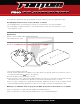
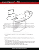
To enter the Data Analysis Mode, at any time, press and hold the Mode and Value buttons together for approximately 2
seconds. In the Data Analysis Mode, your motor RPM, battery low voltage, and ESC temperature can be reviewed, from your
last run. Press the Menu button to scroll through the available data readings. Press and hold the Mode and Value buttons
together, for approximately 2 seconds, to exit the Data Analysis Mode.
A: MIN BATTERY VOLTAGE - Indicates the minimum battery voltage that was reached during operation.
B: MAX ESC TEMP - Indicates the maximum ESC temperature that was reached during operation.
C: MAX MOTOR RPM - Indicates the maximum motor RPM that was reached during operation.
WWW.FANTOMRACING.COM
LCD PROGRAM CARD PARAMETER IDENTIFICATION, FUNCTIONS & DESCRIPTIONS (continued)
B3: BRAKE FORCE - 0% to 100% (12.5% increments – default = 75%) - Use this function to control the
brake force applied to the motor. Increasing the value increases the brake force applied to the motor. The formula for the brake
parameters is: y=ax+b, whereas "y" is brake force, "a" is brake rate, "b" is initial brake, "x" is the throttle, which means the
final brake force is determined by the brake rate and initial brake values.
B4: INITIAL BRAKE RESPONSE - 20 steps (*5) - Use this function to control the initial brake power response to the
motor. Increasing the value increases the initial brake response to the motor. Typically set the value higher for high-traction
tracks and lower for low-traction tracks.
B5: BRAKE RATE - 20 steps (*5) - Use this function to control the overall brake power feeling. Increasing the value
increases the overall brake power feeling. Typically set the value higher for high-traction tracks and lower for low-traction
tracks.
B6: BRAKE FREQUENCY - 1K, 2K, 4K, *8K, 16K - Use this function to control the response feel of the brakes.
Low values provide more aggressive feel. High values provide a smoother feel.
B7: BRAKE CURVE - *Linear, Custom - Use this function to customize the balance between your brake in put and the
ESC brake output. For example, in
"linear" mode, if you push the brake 10%, the ESC will brake 10%. If you push the brake
50%, the ESC will brake 50% and soon. In "custom" mode, you can customize the balance between your brake input and ESC
brake output. For example, you can set it so that when you push the brake 10%, the ESC will brake 25% and so on. The
settings can also be reversed. For example, you can set it so that when you push the brake 10%, the ESC will brake 5% and
so on. Typically use the linear mode with spec motors and the custom mode with modified motors, to increase the brake power
delivery to the higher RPM motors.
B8: OFF BY RADIO - *Yes, No - Select "yes" to enable turning off the ESC by holding the throttle in the full brake
position for 5 seconds. Select "no" to disable this function.
BOOST (T)
NOTE: Boost settings T1 through T3 are not accessible when “*Stock (Blinky)” mode is selected in “G5: RACE MODE”
WARNING: Boost is an advanced feature and should only be used by experienced racers. Improper boost settings can cause
poor performance and/or permanent damage to your ESC and/or motor, which is not covered under warranty.
T1: BOOST TIMING - 0° to 64° (1° increments – default = 0°) - Use this function to control the maximum
amount of dynamic timing the ESC applies to the motor. Boost timing is effective throughout the entire throttle range. Boost
timing starts based on the "BOOST TRIGGER LEVEL" setting. Boost timing is not constant but varies based on throttle
position, starting from the "BOOST TRIGGER LEVEL" point until full throttle.
T2: BOOST TRIGGER LEVEL - 50 steps (*1) - Use this function to set the throttle position that is required to
activate the "BOOST TIMING". Increasing the value increases the amount of advanced throttle that is required to activate the
"BOOST TIMING".
T3: BOOST TRIGGER RATE - 10 steps (*1) - Use this function to set the throttle position that is required to activate
the maximum "BOOST TIMING" that was set in the "BOOST TIMING" function. Increasing the value increases the amount of
advanced throttle that is required to activate maximum "BOOST TIMING".
LCD PROGRAM CARD PARAMETER IDENTIFICATION, FUNCTIONS & DESCRIPTIONS (continued)
G6: DEADBAND - 12 steps (1% increments – default = 4%) - Use this function to adjust the sensitivity of the neutral
position, of the throttle trigger (throttle and braking). In other words, how much the throttle needs to be pulled or pushed
before the ESC will receive input. By changing the value, you can customize how quickly your throttle and braking inputs react
from the neutral position. Lowering the value increases the sensitivity. Raising the value decreases the sensitivity.
G7: BEC OUTPUT - *6v, 7.4v - Use this function to set your BEC output voltage to 6v or 7.4v. You can determine the
correct voltage setting from your servo manual. WARNING: An incorrect BEC voltage setting can cause permanent damage to
your servo.
THROTTLE (TH)
TH1: INITIAL POWER LIMITER - 30 steps (*15) - Use this function to control the initial power to the motor.
Increasing the value increases the initial power delivery to the motor. Typically set the value higher for high-traction tracks and
lower for low-traction tracks.
TH2: THROTTLE RATE - 30 steps (*15) - Use this function to control the overall throttle power feeling. Increasing the
value increases the overall power feeling. Typically set the value higher for high-traction tracks and lower for low-traction
tracks.
TH3: DRIVE FREQUENCY - 1K, 2K, 4K, 8K, *16K - Use this function to control the response feel of the throttle.
Low values provide more aggressive feel. High values provide a smoother feel. Typically use the lower values for spec/stock
motors and the higher values for modified motors.
TH4: RPM LOCK - 1% to *100% (1% increments) - Use this function to lock the motor RPM, typically used for
drift cars. Leave this at the default setting of 100% for all racing applications.
TH5: THROTTLE CURVE - *Linear, Custom - Use this function to customize the balance between your throttle input
and the ESC output. For example, in"linear"mode, if you pull the throttle 10%, the ESC will put out 10% power. If you pull the
throttle 50%, the ESC will put out 50% power and so on. In "custom" mode, you can customize the balance between your
throttle input and ESC output. For example, you can set it so that when you pull the throttle 10%, the ESC will put out 25%
power and so on. The settings can also be reversed. For example, you can set it so that when you pull the throttle 10%, the
ESC will put out 5% power and so on. Typically use the linear mode with modified motors and the custom mode with stock
motors, to increase the power delivery to the motor.
BRAKE (B)
B1: INITIAL BRAKE - 1% to 20% (1% increments – default = 10%) - Use this function to control the instant
brake force to the motor, when the throttle is pushed from the neutral position to the initial brake position. Increasing the value
increases the initial brake force to the motor.
B2: DRAG BRAKE - 0% to 100% (1% increments – default = 10%) - Use this function to control the amount of
automatic brake, when the throttle is returned from the forward to the neutral position. Increasing the value increases the
amount of automatic braking applied to the motor.
LCD PROGRAM CARD PARAMETER IDENTIFICATION, FUNCTIONS & DESCRIPTIONS
GENERAL (G)
G1: RUNNING MODE – *Forward/Brake, Forward/Brake/Reverse, Forward/Reverse – Use this function
to set whether you want forward & brake only, forward and brake and reverse, or forward & reverse only. Most tracks do not
allow reverse during racing. The default setting of “Forward & Brake” only is the recommended setting for all racing applica-
tions.
G2: LOW VOLTAGE CUTOFF - Disable, *Auto, custom 3.0v to 11.1v (0.1v increments) - Over-discharging
a battery will cause permanent damage. To avoid over-discharging the battery, use this function to protect the battery voltage
from being discharged too low. The ESC will stop running, once the chosen minimum battery voltage setting is reached during
operation. Recommended settings:1S=3.3v, 2S=6.6v, 3S=9.9v
G3: ESC OVER-HEAT PROTECTION - Disable, 203˚ Fahrenheit (95˚ Celsius), *221˚ Fahrenheit (*105˚ Celsius), 266˚
Fahrenheit (130˚ Celsius) - Over-heating an ESC will cause permanent damage. To avoid over-heating the ESC, use this function
to protect the ESC temperature from going too high. The power output of the ESC will drop, once the chosen maximum ESC
temperature is reached during operation.
G4: MOTOR ROTATION - *Normal, Reverse - Use this function to change the motor rotation direction (clockwise or
counter-clockwise).
G5: RACE MODE - *Stock (Blinky), Modified - Select "Stock" to run in Blinky mode, typically with 10.5T and over stock/spec
motors. Most tracks require all stock / spec classes to use "Blinky" mode. Select "Modified" to run modified motors, typically
4.5T to 9.5T motors.