
Installation Guide

2
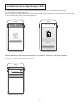
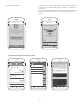
Remote Control Dip Switch Set Up
Figure 7
Dip Switch
Remote
7. If you have multiple fans and want to program all fans to
one handheld control. Slide the Dip Switch with the same
position in ALL receiver to ONE handheld to set up the code
for each fans and follow Step 1 of the remote control speed
set up process. Each fan needs to be no more than 30 feet
from the handheld control that you would like to program.
Please note the wall switch that controls the power to your
fan(s) should be in the off position until you are ready to
program your handheld remote(s).
8. If you have multiple fans and want to program each fan to
separate handheld controls. Slide the Dip Switch with the
same position in both receiver and handheld to set up the
code for each fans and follow Step 1 of the remote control
speed set up process below for each fans. Repeat these steps
for each fan that you would like to program to a separate
handheld remote. Please note that the wall switch that
controls the power to your fan(s) should be in the off position
until you are ready to program your handheld remote(s).
9. To set the remote code with a small screwdriver or ball
point pen (neither included), slide dip switches firmly up or
down to same as receiver unit. (Figure 7)
NOTE: The remote unit has 32 different code
combinations. To prevent possible interference from or
to other remote units, simply change the combination
code in the remote and receiver.
NOTE: Factory setting is all up. Do not use this position .
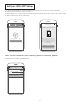
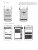
10. Follow the app set up instructions on the following pages.
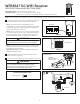
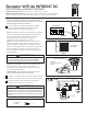
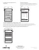
5. The receiver has a wifi antenna that can be used if you
experience range issues. (Figure 6)
6. Restore electrical power at the breaker and wall switch.
WARNING: To avoid possible fire or shock, make sure that
the electrical wires are completely inside the outlet box and
not pinched between the wall plate and the wall.
Figure 6 (Optional)
WIFI antenna
Ceiling
After Installation
WIFI Antenna
mount to ceiling using
wood screw
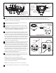
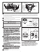
Figure 5
Black
Red
Gray
Yellow
BLK-ANT
Listed
Outlet Box
Green / Yellow
- Ground wire (2)
From Receiver
Green Wire
from Supply
(Ground)
White Wire
from Supply
White Wire
from
Receiver
Listed
Outlet Box
Household
Supply
Black Wire
from Supply
Black / White Wire
from Supply
Green Wire
from Hanger
Bracket (Ground)
Green Wire
from Receiver (2)
(Ground)
Green Wire
from Hanger
Ball (Ground)
Receiver
Green-Ground
wire From Ceiling
Green-Ground
wire From Hanger Bracket
Green-Ground
wire From Hanger Ball
Blue
Black/White
White
4. After connections have been made, put the white and green leads to one side and the black/white leads towards
the other side, upward and carefully push leads into the outlet box. The wires should be spread apart with the
grounded conductor and the equipment-grounding conductor on one side of the outlet box and the ungrounded
conductor on the other side. (Figure 5)