™ The Stafford Ceiling Fan Net Weight 10.54 kg (23.21 lbs) Model No.
Important Safety Instructions WARNING: To avoid fire, shock and serious personal injury, follow these instructions. 1. Read your owner’s manual and safety information before installing your new fan. Review the accompanying assembly diagrams. 2. Before servicing or cleaning unit, switch power off at service panel and lock service panel disconnecting means to prevent power from being switched on accidentally.
LIMITED LIFETIME WARRANTY Extends to the original purchaser of a Fanimation Fan 6. All costs of removal and reinstallation of the fan are the sole responsibility of the owner of the fan and not the store that sold the fan or Fanimation. 7. Fanimation reserves the right to modify or discontinue any product at any time and may substitute any part under this warranty. 8. Under no circumstances may a fan be returned without prior authorization from Fanimation.
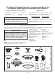
This manual is designed to make it as easy as possible for you to assemble, install, operate, and maintain your ceiling fan Tools Needed for Assembly • One Phillips head screwdriver • One stepladder • One ¼˝ blade screwdriver Materials • One wire stripper • Three wire connectors (supplied) Wiring outlet box and box connectors must be of type required by local code.
Energy Efficient Use of Ceiling Fans Ceiling fan performance and energy savings rely heavily on the proper installation and use of the ceiling fan. Here are a few tips to ensure efficient product performance. Using the Ceiling Fan Year Round Summer Season: Use the ceiling fan in the counterclockwise direction. The airflow produced by the ceiling fan creates a wind-chill effect, making you “feel” cooler. Select a fan speed that provides a comfortable breeze, lower speeds consume less energy.
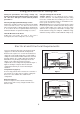
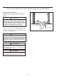
Electrical and Structural Requirements (Continued) Deep box with brace (Figure 3) Paired with a deep box, this hanger is meant to span between two joists and takes the place of wooden blocking. CEILING JOIST WARNING To reduce the risk of fire, electric shock, or personal injury, mount to outlet box marked acceptable for fan support of 15.9 kg (35 lbs) or less and use mounting screws provided with the outlet box.
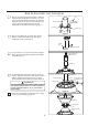
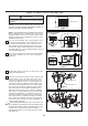
How to Assemble Your Ceiling Fan 1. Remove the hanger ball portion from the downrod /hanger ball assembly by loosening the set screw in the hanger ball until the ball falls freely down the downrod. Remove the pin from the downrod, then remove the hanger ball. Retain the pin and hanger ball for reinstallation in Step 6 (Figure 1). Pin Downrod Set Screw Hanger Ball Figure 1 2. Remove the hairpin clip and clevis pin from the bottom of downrod.
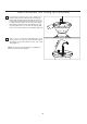
How to Assemble Your Ceiling Fan (continued) 6. Reinstall the hanger ball on the downrod as follows. Route the three 80-inch wires through the hanger ball. Position the pin through the two holes in the downrod and align the hanger ball so the pin is captured in the groove in the top of the hanger ball. Pull the hanger ball up tight against the pin. Securely tighten the set screw in the hanger ball. A loose set screw could create fan wobble (Figure 6). Figure 6 7.
How to Hang Your Ceiling Fan WARNING To avoid possible ſre or shock, be sure electricity is turned off at the main fuse box before hanging. (Figure 1) MAIN FUSE BOX NOTE: If you are not sure if the outlet box is grounded, contact a licensed electrician for advise, as it must be grounded for safe operation. Figure 1 WARNING CEILING The fan must be hung with at least 7’ of clearance from ƀoor to blades. (Figure 2) NO LESS THAN 7 FEET FLOOR Figure 2 1.
How to Wire Your Ceiling Fan WARNING To avoid possible electrical shock, be sure electricity is turned off at the main fuse box before hanging (Figure 1). MAIN FUSE BOX NOTE: If you are not sure if the outlet box is grounded, contact a licensed electrician for advice, as it must be grounded for safe operation. NOTE: The hand-held remote included with this fan has 16 different code combinations.
How to Install Your Canopy Housing NOTE: This step is applicable after the neccessary wiring is completed. 1. Remove one of the two shoulder screws in the hanger bracket. Loosen the second shoulder screw without fully removing it. Assemble canopy by rotating key slot in canopy over shoulder screw in hanger bracket. Tighten shoulder screw. Fully assemble and tighten second shoulder screw that was previously removed.
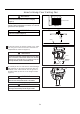
How to Assemble the Blades and Light Kit 3. Remove one of the three screws in the support bracket at the bottom of the motor assembly. Slightly loosen the remaining two screws and retain the removed screw (Figure 3). Motor Assembly Figure 3 4. Connect the black wire from the socket plate assembly to the black wire from the motor assembly, and the white wire from the socket plate assembly to the white wire from the motor assembly (Figure 4).
How to Assemble the Blades and Light Kit (continued) 7. Remove the finial, trim cover and nut from post on light plate assembly (Figure 7). Light Plate Assembly Nut Trim Cover Finial Figure 7 8. Insert light bulbs into sockets (Figure 8). Bulb Figure 8 9. Position the glass onto the socket plate assembly and secure with nut, trim cover and finial. Do not overtighten (Figure 9).
How to Operate Your Ceiling Fan 1. IMPORTANT: Using a full range dimmer switch (not included) to control fan speed will damage the fan. To reduce the risk of fire or electrical shock, do not use a full range dimmer switch to control the fan speed. (Figure 1) For illustrative purposes only-not intended to cover all types of controls Figure 1 2. Restore electrical power to the outlet box by turning the electricity on at the main fuse box (Figure 2).
How to Install Your Remote Control (Option #1) 1. Unthread two screws from the wall switch plate. (Figure 1) 2. Install the control bracket with two #6-32x 3/4” screws. Push the four plastic plugs in to cover the screw holes. (Included in the control packaging). (Figure 2) Figure 1 Figure 2 How to Install Your Remote Control (Option #2) 1. Unthread two screws from the wall switch plate. (Figure 1) 2. Install the control bracket with two #6-32x 1” screws.
Trouble Shooting WARNING For your own safety turn off power at fuse box or circuit breaker before trouble shooting your fan. Trouble Probable Cause 1. Fuse or circuit breaker blown. 1.FAN WILL NOT START 2. Loose power line connections to the fan, or loose switch wire connections in the switch housing. 3. Reversing switch in neutral position. 4. Dead battery in remote control. 1. Blades not attached to fan. 2. Loose screws in motor housing. 2.FAN SOUNDS NOISY 3.
Parts List Model No.
™ The Stafford Model PL8274** Exploded-View Illustration 1 14 13 2 3 4 5 6 15 8 7 15 9 12 15 11 10 Figure 1 NOTE: The illustration shown is not to scale or its actual con¿guration may vary. Product/parts are subject to change without notice.
Copyright 2015 Fanimation 10983 Bennett Parkway Zionsville, IN 46077 (888) 567-2055 FAX (866) 482-5215 Outside U.S. call (317) 733-4113 Visit Our Website @ www.fanimation.com 2015/01 V.
™ The Stafford Ventilador de techo Peso neto 10.54 kg (23.21 lbs) Modelo N.
Instrucciones de seguridad importantes ADVERTENCIA: Siga estas instrucciones para prevenir incendios, descargas eléctricas y lesiones personales graves. 1. Lea el manual del propietario y la información de seguridad antes de instalar su nuevo ventilador. Observe los diagramas de ensamblaje adjuntos. 2. Antes de llevar a cabo el mantenimiento o la limpieza de la unidad, desconecte la electricidad en el panel de servicio y bloquee los medios de desconexión del mismo para evitar que se active accidentalmente.
GARANTÍA LIMITADA DE POR VIDA Se extiende al comprador original de un ventilador Fanimation 6. Todos los gastos de remoción y reinstalación del ventilador son responsabilidad exclusiva del propietario, y no de la tienda que vendió el ventilador ni de Fanimation. 7. Fanimation se reserva el derecho de modificar o discontinuar un producto en cualquier momento, o sustituir cualquier pieza según lo establecido por esta garantía. 8.
Este manual está diseñado para facilitar al máximo el ensamblaje, la instalación, el funcionamiento y el mantenimiento de su ventilador de techo. Herramientas necesarias para el ensamblaje • Destornillador Phillips • Escalera de tijera • Destornillador de ¼˝ Materiales • Pelacables • Tres conectores de cables (incluidos) ADVERTENCIA Antes de ensamblar el ventilador de techo, consulte la sección sobre el método correcto de instalación eléctrica del ventilador (página 30).
8VR HÀFLHQWH GH OD HQHrJtD HQ vHQWLODGRrHV GH WHcho El nivel de rendimiento y ahorro de energía de los ventiladores de techo dependen de su correcta instalación yuso.Acontinuaciónlepresentamosalgunassugerencias para asegurar un rendimiento eficiente del producto. Uso del ventilador de techo todo el año En verano: Use el ventilador de techo en sentido contrario a las agujas del reloj. El flujo de aire que produce el ventilador creará un efecto frío del aire que lo refrescará más.
Requisitos eléctricos y estructurales (cont.) No bloqueo (Figura 3) Conectado a una caja de distribución eléctrica, este colgador sirve para abarcar el espacio entre dos vigas y ocupar el lugar de bloqueo de la madera. Vigas del techo ADVERTENCIA Para reducir el riesgo de incendios, descargas eléctricas o lesiones personales, fije el ventilador a la caja de distribución eléctrica marcada como aceptable para soporte de ventilador de 15,88kg (35lb).
Cómo ensamblar el ventilador de techo 1. Extraiga la pieza de la bola colgante de la unidad de la bola colgante / varilla aflojando el tornillo de presión de la bola colgante hasta que la bola se libere de la varilla. Retire el pasador del barral y luego extraiga la semiesfera. Conserve el pasador y la semiesfera para su reinstalación en el Paso 6 (Figura 1). Pasador Bola para colgar Ranura de la bola colgante Tornillo de fijación Figura 1 2 Retire .
Cómo ensamblar el ventilador de techo (cont.) 6. Vuelva a colocar la semiesfera en el barral como se indica a continuación. Pase los tres cables de a través de la semiesfera. Pase el 2.03 m pasador a través de los dos orificios en el barral y alinee la semiesfera de modo que el pasador quede atrapado en la ranura de la parte superior de la misma. Empuje la semiesfera hacia arriba, bien ajustada contra el pasador. Ajuste firmemente el tornillo de fijación en la semiesfera.
Cómo colgar el ventilador de techo ADVERTENCIA Para evitar una posible descarga eléctrica, asegúrese de cortar la alimentación eléctrica de la caja de fusibles principal antes de colgar el ventilador. (Figura 1) PRINC IPAL CAJA DE FUSIBLES NOTA: Si no está seguro de si la caja de salida tiene conexión a tierra, pida consejo a un electricista certificado, ya que debe tener conexión a tierra para un funcionamiento seguro.
Cómo realizar la instalación eléctrica del ventilador de techo ʆADVERTENCIA Para evitar posibles descargas eléctricas, asegúrese de que la electricidad esté desconectada en la caja de fusibles principal antes de realizar la instalación eléctrica. (Figura 1) NOTA: Si no está seguro de si la caja de distribución eléctrica tiene conexión a tierra, pida asesoramiento a un electricista autorizado, ya que la conexión a tierra es fundamental para un funcionamiento seguro.
Cómo instalar la carcasa de la cubierta NOTA: Este paso se debe realizar luego de completar la completed instalación eléctrica necesaria. ADVERTENCIA Para evitar posibles incendios o descargas eléctricas, asegúrese de que los cables eléctricos vuelta hacia arriba y completamente empujarse con cuidado en el cuadro de juntura y de que no estén aprisio el techo. Cubierta de unión del motor Figura 1 1. Extraiga una de los tornillos de hombro en el soporte del gancho.
Cómo ensamblar las Aspas y Kit de luz (cont.) 3. Extraiga uno de los tres tornillos del soporte ubicado en la parte inferior de la unidad del motor. Afloje levemente los otros dos tornillos y conserve el tornillo retirado. (Figura 3) Unidad del motor Figura 3 4. Conecte el cable negro desde ensamble de la placa del portalámpara al cable negro ensamble del motor y conecte el cable blanco desde ensamble de la placa del portalámpara al cable blanco ensamble del motor.
Cómo ensamblar las Aspas y Kit de luz (cont.) 7. Retire el remate del reborde,la tapa y la tuerca, el del ensamble de la placa de iluminación. (Figura 7) Ensamble de la placa de iluminación Tuerca Tapa Reborde Figura 7 8. Introduzca la bombillas en la conexións. (Figura 8) Bombilla Figura 8 9. Coloque el vidrio en ensamble de la placa del portalámpara y fíjelo con el tuerca, la tapa y remate del reborde que retiró anteriormente. No apriete demasiado.
Cómo utilizar su ventilador de techo 1. IMPORTANTE: El uso de un regulador de la intensidad completa (no incluido) para controlar la velocidad del ventilador dañará el dispositivo. Para reducir el riesgo de incendio o descarga eléctrica, no utilice dicho regulador para controlar la velocidad del ventilador. (Figura 1) Solo para referencia visual-no ha sido diseñado para cubrir todos los tipos de controles Figura 1 2.
Cómo instalar su mando a distancia (Opción #1) 1. Retire los dos tornillos colocados en la plaza del interruptor de la pared. (Figura 1) 2. Instale el soporte de control con los dos tornillos #6-32x 3/4”. Empuje los cuatro tapones de plástico para cubrir los orificios de los tornillos. (Incluidos con el mando). (Figura 2) Figura 1 Figura 2 Cómo instalar su mando a distancia (Opción #2) 1. Retire los dos tornillos colocados en la plaza del interruptor de la pared. (Figura 1) 2.
Solución de problemas ʆADVERTENCIA Para su propia seguridad, desconecte la electricidad de la caja de fusibles o disyuntor antes de solucionar problemas en su ventilador. Problema 1. EL VENTILADOR NO ARRANCA Causa posible Solución sugerida 1. El fusible o el disyuntor están fundidos. 1. Controle los fusibles del circuito principal y derivado o los disyuntores. 2. Las conexiones eléctricas del ventilador o del interruptor en la caja del interruptor están flojas. 2.
Lista de piezas Modelos N.° PL8274** N.° de Ref. Pieza # N.
™ The Stafford Modelo PL8274** Ilustración del despiece 1 14 13 2 3 4 5 6 15 8 7 15 9 12 15 11 10 Figura 1 NOTA: la ilustración que se muestra no está hecha a 38
Copyright 2015 Fanimation 10983 Bennett Parkway Zionsville, IN 46077 Llame sin cargo al (888) 567-2055 FAX (866) 482-5215 Desde fuera de los EE.UU., llame al (317) 733-4113 Visite nuestro sitio Web en www.fanimation.com 2015/01 V.