
Installation & Assembly

Copyright 2020 Fanimation
2020/05 V.01
10983 Bennett Parkway
Zionsville, IN 46077
(888) 567-2055 • FAX (866) 482-5215
Outside U.S. call (317) 733-4113
WWW.FANIMATION.COM
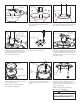
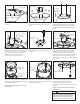
13. Attach the safety cable to ceiling
support cable. Slide cable clamp and
washer onto safety cable (from fan).
Place the end of cable through the loop
of ceiling support cable. Pull as much
cable through loop as possible. Feed end
of cable into clamp hole and firmly tighten
screw.
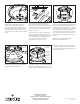
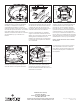
15. Lift the fan off the bracket hook and
mount your fan by sliding the ceiling canopy
over the mounting bracket with the two
loosened screws going into the “ L” slots in
the canopy. Be sure all wiring is tucked into
the ceiling canopy and is not pinched.
Once the canopy is flush with your ceiling,
turn clockwise to seat the screws into the
keyed portion of the slot and tighten the
screws.
Connect your fan’s wiring according to
Spitfire ceiling fan owners manual. If you
have misplaced your owners manual one
can be downloaded at fanimation.com
or contact a licensed electrician to
complete the wiring of your fan.
14. Lift your fan motor assembly and
hang it from the ceiling bracket hook
through one of the two screw holes in the
canopy lip. Do not use the grooved slots.
You can now proceed with the electrical
wiring of your fan.
Ceiling
Bracket
Ceiling
Bracket
Ceiling
Ceiling
Canopy
Bracket
16. Install the remaining two screws
removed in Step 2 to secure the ceiling
canopy to the ceiling bracket.
17.
Push the screw trim cover ring up to
conceal the screws, such that the mounting
tabs seat into the dimpled grooves in the
ceiling canopy midway between the screws.
Ceiling
Canopy
Slot
Screw
NOTE: SUPPLY WIRES HAVE BEEN
OMITTED FROM DIAGRAM.
Dimpled
Groove
Mounting
Tabs(4)
Screw Trim
Cover Ring
Installation of your close-to-ceiling kit is
complete. Reference your owners manual
for any additional assembly steps required
for Spitfire ceiling fan.