
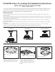
Installation & Assembly
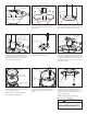
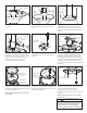

4. Remove the hanger ball set screw. 5. Remove the pin from the downrod,
then remove the hanger ball and the
ceiling canopy.
6. Remove the motor coupling cover screw
from motor assembly using an allen wrench,
then remove the motor coupling cover.
Hanger Ball
Hanger
Ball
Pin
Ceiling
Canopy
Motor Coupling
Cover
Motor Coupling
Cover
Motor
Coupling
Cover
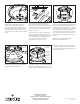
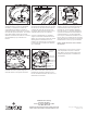
7. Remove the hairpin clip, clevis pin and 8. Remove the fours screws in the motor
coupler and retain for Step 11.screws with nuts from the bottom of
downrod. Retain the pin, clip and screws
with nuts for reinstallation in Step 9.
Then Remove the downrod.
9. Insert motor coupler into the downrod
support on top of the motor. Reinstall the
clevis pin by aligning the holes in the motor
coupler. Secure clevis pin with hairpin clip
and tighten the two set screws with nuts in
the motor coupler.
10. Route wires and safety cable through
motor coupling cover, screw trim cover
ring and ceiling canopy.
Screws and
Locking Nuts (2)
Screws and
Locking Nuts (2)
Clevis Pin
Clevis Pin
Hairpin
Clip
Hairpin Clip
Downrod
Ceiling
Canopy
Ceiling
Canopy
Screw Trim
Cover Ring
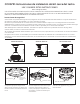
11. Align the four holes in the ceiling
canopy to motor coupling cover and
secure using the previously removed
screws.
12. Using the two screws and washers,
securely attach the ceiling bracket to the
ceiling junction box, making sure the
supply wires pass through the hole in the
center of the bracket.
WARNING
To avoid possible electrical shock,
main fuse box before hanging.
NOTE: SUPPLY WIRES HAVE BEEN
OMITTED FROM DIAGRAM.
NOTE: SUPPLY WIRES HAVE BEEN
OMITTED FROM DIAGRAM.
Ceiling
Bracket
Junction
Box
Motor Coupler
Motor Coupler