ODYN CUSTOM CEILING FAN ™ MODEL #MAD8152** 6 Español p. 29 ATTACH YOUR RECEIPT HERE AND REGISTER YOUR FAN AT FANIMATION.COM READ AND SAVE THESE INSTRUCTIONS Date Code Purchase Date Net Weight 25.91 lbs (11.75 kgs) For best and quickest service please provide date code. You can find the date code on the carton, hand-held remote (inside of the battery compartment), receiver or top of fan housing.
Important Safety Instructions WARNING: To avoid fire, shock and serious personal injury, follow these instructions. 1. Read your owner’s manual and safety information before installing your new fan. Review the accompanying assembly diagrams. 2. Before servicing or cleaning unit, switch power off at service panel and lock service panel disconnecting means to prevent power from being switched on accidentally.
LIMITED LIFETIME WARRANTY Extends to the original purchaser of a Fanimation fan from an authorized Fanimation dealer/retailer only 1. LIMITED LIFETIME MOTOR WARRANTY - If any part of your fan motor fails, due to a defect in materials or workmanship during the lifetime of the original purchaser, Fanimation will provide the replacement part free of charge, when the defective fan is returned to our national service center. Proof of purchase is required.
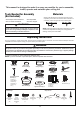
This manual is designed to make it as easy as possible for you to assemble, install, operate and maintain your ceiling fan Materials Tools Needed for Assembly (Not Included) • One Phillips head screwdriver • One ¼˝ blade screwdriver Wiring outlet box and box connectors must be of type required by local code.
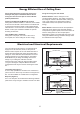
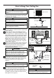
Energy Efficient Use of Ceiling Fans Ceiling fan performance and energy savings rely heavily on the proper installation and use of the ceiling fan. Here are a few tips to ensure efficient product performance. Using the Ceiling Fan Year Round Choosing the Appropriate Mounting Location Ceiling fans should be installed, or mounted, in the middle of the room and at least 7 feet from floor to the blade and 18 inches from wall to the blade.
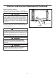
Electrical and Structural Requirements (Continued) Deep box with brace (Figure 3) Paired with a deep box, this hanger is meant to span between two joists and takes the place of wooden blocking. CEILING JOIST WARNING To reduce the risk of fire, electric shock, or personal injury, mount to outlet box marked acceptable for fan support of 15.9 kg (35 lbs) or less and use mounting screws provided with the outlet box.
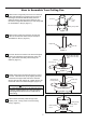
How to Assemble Your Ceiling Fan 1. Remove the hanger ball portion from the downrod/ hanger ball assembly by loosening the set screw in the hanger ball until the ball falls freely down the downrod. Remove the pin from the downrod, then remove the hanger ball. Retain the pin and hanger ball for reinstallation in Step 6. (Figure 1) Pin Downrod Set Screw Hanger Ball Figure 1 2. Remove the hairpin clip and clevis pin from the bottom of the downrod. Retain the pin and clip for reinstallation in Step 4.
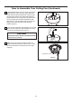
How to Assemble Your Ceiling Fan (Continued) 6. Reinstall the hanger ball on the downrod as follows. Route the brown, blue, red, gray, yellow wires and safety cable through the hanger ball. Position the pin through the two holes in the downrod and align the hanger ball so the pin is captured in the groove in the top of the hanger ball. Pull the hanger ball up tight against the pin. Securely tighten the set screw in the hanger ball. A loose set screw could create fan wobble. (Figure 6) in. o9 6t 7.
How to Hang Your Ceiling Fan WARNING To avoid possible fire or shock, be sure electricity is turned off at the main fuse box before hanging. (Figure 1) Main Fuse Box NOTE: If you are not sure if the outlet box is grounded, contact a licensed electrician for advice, as it must be grounded for safe operation. Figure 1 WARNING Ceiling The fan must be hung with at least 7’ of clearance from floor to blades. (Figure 2) CAUTION Floor Do not connect fan blades until the fan is completely installed.
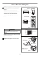
How to Wire Your Ceiling Fan NOTE: If fan or supply wires are different colors than indicated, have this unit installed by a qualified electrician. 1. To set the code on receiver unit, slide dip switches to the same positions as set on the remote control. (Figure 1) Receiver Dip Switch ON NOTE: The remote unit has 32 different code combinations. To prevent possible interference from or to other remote units, simply change the combination code in the remote and receiver.
How to Wire Your Ceiling Fan (Continued) BROWN RED GRAY GROUND YELLOW YELLOW GRAY YELLOW / GREEN (2) HANGER BALL RED HANGER BRACKET BROWN RED BLUE L1 WHITE AC POWER BLUE BLACK N BLACK WHITE L DC MOTOR RECEIVER WHITE BLUE BLACK ANTENNA LIGHT KIT Figure 4 CAUTION: INCORRECT WIRE CONNECTION COULD DAMAGE THIS RECEIVER. 3. Connect wires using connectors as shown in Figure 4.
How to Wire Your Ceiling Fan (Continued) 5. The receiver has a wifi antenna that can be used if you experience range issues.
How to Install Your Canopy Housing NOTE: This step is applicable after the neccessary wiring is completed. 1. Assemble canopy by rotating key slot in canopy over shoulder screw in hanger bracket, taking care not to pinch the wires. Tighten shoulder screw. Fully assemble and tighten second shoulder screw that was previously removed.
How to Assemble Your Ceiling Fan Blades 1. Lay flat side of blade holder on a flat surface with the inside of the blade holder facing up. This is the side with the threaded posts and pitched foot. Position the blade over the blade holder with the threaded posts showing. Make sure the bottom edge of the blade is fully seated against the blade holder. Place blade cover on top of the blade, positioning the holes over the threaded posts.
How to Assemble Your Light Kit Assembly or Cap 1. Remove the six screws in the support bracket at the bottom of the motor assembly. Assemble the light plate assembly to the support bracket using the previously removed screws. (Figure 1) Light Plate Assembly Figure 1 2. Remove the three screws in the light plate assembly. Assemble the light kit assembly to the light plate assembly using the previously removed screws. (Figure 2) Light Plate Assembly 3.
How to Operate Your Ceiling Fan 1. IMPORTANT: Using a full range dimmer switch (not included) to control fan speed will damage the fan. To reduce the risk of fire or electrical shock, do not use a full range dimmer switch to control the fan speed. (Figure 1) 2. Restore electrical power to the outlet box by turning the electricity on at the main fuse box.
How to Operate Your Ceiling Fan (Continued) 5. If you have multiple fans and want to program all fans to one handheld control. Slide the Dip Switch with the same position in ALL receiver to ONE handheld to set up the code for each fans and follow Step 1 of the remote control speed set up process. Each fan needs to be no more than 30 feet from the handheld control that you would like to program.
How to Operate Your Ceiling Fan (Continued) 8. Remote Control Speed (RPM) Setting Process : (Figure 6) 1) After installing and wiring the unit, restore power to your fan by ensuring that the breaker and wall switch that controls the power supply is moved to the on position, press and hold the “LEARN” button inside of the battery compartment of the handheld remote control for 1-3 seconds. 2) You must press the “LEARN” button within 30 seconds of restoring power to the fan.
How to Operate Your Ceiling Fan (Continued) 10. Remote functions: (Figure 8) • Indicator LED light: fan speed and light dimmer indicator • button: Tap once to turn off the fan. Press and hold this button for 5 seconds to turn on or turn off the buzzer. • Fan Speed: Turn on fan and turn speed up. Turn on fan and turn speed down. • Light button: Turn ON\OFF the light. Increase light output level. Decrease light output level. • Sleep Timer: The fan and light will turn off after 1 hour.
How to Set Up the fanSync WiFi APP 1. Visit the Apple APP Store or the Google Play Store to download the free fanSync WiFi APP. Create your Fanimation fanSync account. (Figure 1) 10:37 AM All 80% Home Your dashboard is empty Add a Fanimation Ceiling Fans Figure 1 2. At this stage, your ceiling fan WiFi receiver should be installed and within range of your WiFi router. With the APP open, select "add device". (Figure 2) 10:37 AM 80% Add Fainmation..
How to Set Up the fanSync WiFi APP (Continued) 4. Select your WiFi router and enter the WiFi password to connect your fanSync WiFi receiver. It will take 1-2 minutes to connect. After your WiFi receiver is connected, you can now name your ceiling fan in the APP and customize your settings. (Figure 4) 10:40 AM 80% Add Fainmation.. Set Up Wi-Fi Network Enter your network settings below to connect your device online. SSID XXXXX PASSWORD Remember my SSID and pa...
How to Set Up the fanSync WiFi APP (Continued) ● Share Device After one smart device is connected to a fan, you must share the device with other users in order to control the fan with their device's APP. 10:45 AM 80% Settings DEVICE NAME Lounge Save EXTRA DEVICE CONTROLS ! HIDE FAN DIRECTION HIDE LIGHT POWER HIDE LIGHT DIMMER FAMILY SHARING SHARE DEVICE ● Link with Amazon Echo, Google Home and IFTTT Select the device you want to connect and follow the instructions in the set up procedure.
How to Install Your Remote Control 1. Installing Wall Plate: (Figure 1) Attach wall plate using the two provided screws. Figure 1 Maintenance Periodic cleaning of your new ceiling fan is the only maintenance necessary. When cleaning, use only a soft brush or lint free cloth to avoid scratching the finish. Abrasive cleaning agents are not required and should be avoided to prevent damage to finish. CAUTION Do not use solvents when cleaning your ceiling fan.
Troubleshooting WARNING For your own safety turn off power at fuse box or circuit breaker before trouble shooting your fan. Trouble Probable Cause 1. Fuse or circuit breaker blown. 1. FAN WILL NOT START Suggested Remedy 2. Loose power line connections to the fan, or loose switch wire connections in the switch housing. 1. Check main and branch circuit fuses or circuit breakers. 2. Check line wire connections to fan and switch wire connections in the switch housings. 3. Dead battery in remote control.
Parts List Model #MAD8152** Ref.
Fan Blades--Sold Separately 1 BPW8152-72** BPW8152-64** BPW8152-56** Blade Set NOTE: The illustration shown is not to scale or its actual configuration may vary. Before discarding packaging materials, be certain all parts have been removed. How To Order Parts When ordering repair parts, always give the following information: • Fan Model Number • Part Number • Part Description • Date Code Contact techsupport@fanimation.com or call 1.888.567.2055 for repair parts.
Odyn™ Custom Model MAD8152** Exploded-View Illustration 1 15 2 3 4 5 6 15 7 15 purchased separately 8 9 10 11 12 13 14 15 NOTE: The illustration shown is not to scale or its actual configuration may vary. Product/parts are subject to change without notice.
10983 Bennett Parkway Zionsville, IN 46077 Phone: 888-567-2055 Outside U.S.: 317-733-4113 FAX: 866-482-5215 FANIMATION.COM 2021/03 V.
VENTILADOR DE TECHO ODYN ™ CUSTOM MODELO #MAD8152** 6 ADJUNTE SU RECIBO AQUÍ Y REGISTRE SU VENTILADOR EN FANIMATION.COM LEA Y GUARDE ESTAS INSTRUCCIONES Código de fecha Fecha de compra Peso neto 11.75 kgs (25.91 lbs) Para ofrecer un servicio rápido y de calidad, por favor suministre el código de fecha. Puede encontrar el código de fecha en el paquete, en el mando a distancia (dentro del compartimento de las pilas), en el receptor o en la parte superior de la carcasa del ventilador.
Instrucciones de seguridad importantes ADVERTENCIA: Siga estas instrucciones para prevenir incendios, descargas eléctricas y lesiones personales graves. AVERTISSEMENT: Suivez ces instructions pour éviter un incendie, une électrocution et des blessures graves. 1. Lea el manual del propietario y la información de seguridad antes de instalar su nuevo ventilador. Observe los diagramas de ensamblaje adjuntos. 2.
GARANTÍA LIMITADA DE POR VIDA Se extiende al comprador original del ventilador Fanimation solo desde un distribuidor/minorista autorizado de Fanimation 1.
Instrucciones para el desempaque Para su comodidad, marque cada uno de los pasos. A medida que completa cada paso, coloque una marca de verificación. Con esto se asegurará de completar todos los pasos y podrá saber desde dónde retomar si fuera interrumpido. ADVERTENCIA AVERTISSEMENT No instale ni utilice el ventilador si falta alguna pieza o si hay piezas dañadas.
Uso eficiente de la energía en ventiladores de techo El nivel de rendimiento y ahorro de energía de los ventiladores de techo dependen de su correcta instalación y uso. Acontinuación le presentamos algunas sugerencias para asegurar un rendimiento eficiente del producto.
Requisitos eléctricos y estructurales (cont.) Uso del soporte (Figura 3) Conectado a una caja de distribución eléctrica, este colgador sirve para abarcar el espacio entre dos vigas y ocupar el lugar de bloqueo de la madera. Vigas del techo ADVERTENCIA Para reducir el riesgo de incendios, descargas eléctricas o lesiones personales, fije el ventilador a la caja de distribución eléctrica marcada como aceptable para soporte de ventilador de 15,88kg (35lb).
Cómo ensamblar el ventilador de techo 1. Extraiga la pieza de la bola colgante de la unidad de la bola colgante / varilla aflojando el tornillo de presión de la bola colgante hasta que la bola se libere de la varilla. Retire el pasador del barral y luego extraiga la semiesfera. Conserve el pasador y la semiesfera para su reinstalación en el Paso 6. (Figura 1) Pasador Varilla Tornillo de fijación Bola colgante Figura 1 2.
Cómo ensamblar el ventilador de techo (cont.) 6. Vuelva a colocar la semiesfera en el barral como se indica a continuación. Pase los cables de marrón, azul, rojo, gris, amarillo y cable de soporte para techo a través de la semiesfera. Pase el pasador a través de los dos orificios en el barral y alinee la semiesfera de modo que el pasador quede atrapado en la ranura de la parte superior de la misma. Empuje la semiesfera hacia arriba, bien ajustada contra el pasador.
Cómo colgar el ventilador de techo ADVERTENCIA Para evitar una posible descarga eléctrica, asegúrese de cortar la alimentación eléctrica de la caja de fusiblesprincipal antes de colgar el ventilador. (Figura 1) Principal Caja De Fusibles AVERTISSEMENT Figura 1 Assurez-vous que l'alimentation électrique est coupée au niveau du boîtier à fusibles principal avant de suspendre le ventilateur afin d'éviter tout risque d'électrocution.
Cómo colgar el ventilador de techo (cont.) 3. Asegúrese de que los cables de suministro eléctrico, incluido el cable de conexión a tierra del soporte de suspensión y el cable de seguridad, hayan atravesado el barral, entre el soporte de suspensión y la caja de conexiones, de modo que más tarde se pueda realizar la instalación eléctrica. 4. Levante cuidadosamente el ventilador y coloque el ensamble de la bola para colgar/varilla en la abrazadera para colgar que acaba de fijar a la caja de salida.
Cómo realizar la instalación eléctrica del ventilador de techo NOTA: Si los cables de suministro o del ventilador son de colores diferentes que los indicados, contrate a un electricista calificado para que realice la instalación. 1. Para configurar el código de unidad del receptor. Deslice los interruptores de código a las mismas posiciones que en el transmisor. (Figura 1) Receptor Interruptores ON 1 NOTA: El mando a distancia incluido en este ventilador tiene 32 combinaciones diferentes de códigos.
Cómo realizar la instalación eléctrica del ventilador de techo (cont.) Gris Rojo Gris Amarillo Amarillo Rojo Marrón Puesta a tierra Abrazadera para colgar Bola para colgar Amarillo / Verde (2) Blanco Marrón N L1 Azul Negro Blanco Rojo Azul L Negro ALIMENTACIÓN DE CA DC de MOTOR Receptor Blanco Antena Negro Azul Kit De Luz Figura 4 3. Realice las conexiones de cables al bloque del terminal como se muestra en la Figura 4.
Cómo realizar la instalación eléctrica del ventilador de techo (cont.) 5. El receptor tiene una antena Wifi que puede utilizarse si sufre problemas de rango. (Figura 6) Después de la instalación Techo Figura 6 (Opcional) Instale la antena WIFI en el techo usando un tornillo para madera Antena WIFI Cómo instalar la carcasa de la cubierta NOTA: Este paso se debe realizar luego de completar la instalación eléctrica necesaria. 1.
Cómo ensamblar las aspas del ventilador de techo 1. Apoye el lado liso del soporte de aspas sobre una superficie plana, con la parte interior del soporte mirando hacia arriba. Este es el lado que tiene los pilotes roscados y la base inclinada. Coloque las aspas sobre sus soportes con los postes roscados que se muestran. Asegúrese de que el borde inferior del aspa esté completamente asentado sobre el brazo del aspa.
Cómo ensamblar su el kit de iluminación o la tapa 1. Extraiga los seis tornillos del soporte ubicado en la parte inferior de la unidad del motor. Instale la unidad de la placa de luz en al soporte utilizando los tornillos retirados previamente. (Figura 1) Unidad de la placa de luz Figura 1 2. Extraiga los tres tornillos de la unidad de la placa de luz. Instale la ensamble de kit de luz en al unidad de la placa de luz utilizando los tornillos retirados previamente.
Cómo ensamblar su el kit de iluminación o la tapa (cont.) 4. Instale la unidad de luz LED utilizando utilizar los tornillos que retiró en el paso 3A. (Figura 4) PRECAUCIÓN La fuente de luz está diseñado para esta aplicación específica y puede recalentarse si reparado por personal no capacitado. Si se requiere ningún tipo de servicio, el producto debe ser devuelto a un centro de servicio autorizado para su revisión o reparación.
Cómo utilizar su ventilador de techo 1. IMPORTANTE: El uso de un regulador de la intensidad completa (no incluido) para controlar la velocidad del ventilador dañará el dispositivo. Para reducir el riesgo de incendio o descarga eléctrica, no utilice dicho regulador para controlar la velocidad del ventilador. (Figura 1) 2. Restaure la fuente de alimentación de la toma de corriente enciendo la electricidad del fusible principal.
Cómo utilizar su ventilador de techo (cont.) 5. Si tiene varios ventiladores y desea programarlos todos en un único mando a distancia, Deslice el interruptor DIP a la misma posición en TODOS los receptores a UN dispositivo móvil para configurar el código de cada ventilador y siga el Paso 1 del proceso de configuración de la velocidad del mando a distancia. Paso 1 del proceso de configuración del mando a distancia.
Cómo utilizar su ventilador de techo (cont.) 9. Vuelva a colocar la cubierta de la batería en el mando a distancia con un tornillo retirados previamente. (Figura 7) 10. Funciones del control remoto: (Figura 8) • Luz LED del indicador: Velocidad del ventilador e indicador atenuante de la iluminación • Botón: Toque este botón apaga el ventilador. Mantenga pulsado el botón durante 5 segundos para encender o apagalo el zumbador. • Velocidad del ventilado: Enciende el ventilador y aumenta la velocidad.
Configuración de la App fanSync Wifi 1. Visite el App Store de Apple o el Play Store de Google para descargarse la App gratuita fanSync Wifi. Cree su cuenta Fanimation fanSync. (Figura 1) 10:37 AM All 80% Home Your dashboard is empty Add a Fanimation Ceiling Fans Figura 1 2. En este paso, el receptor Wifi de su ventilador de techo debe estar instalado y dentro del rango de su router Wifi. Con la App abierta, seleccione “añadir dispositivo”. (Figura 2) 10:37 AM 80% Add Fainmation..
Configuración de la App fanSync Wifi (cont.) 4. Seleccione su router Wifi e introduzca la contraseña Wifi para conectarse a su receptor Wifi fanSync. Tardará 1 - 2 minutos en conectarse. Una vez que su receptor Wifi se haya conectado, ahora puede nombrar su ventilador de techo en la App y personalizar sus ajustes. (Figura 4) 10:40 AM 80% Add Fainmation.. Set Up Wi-Fi Network Enter your network settings below to connect your device online. SSID XXXXX PASSWORD Remember my SSID and pa...
Configuración de la App fanSync Wifi (cont.) ● Compartir dispositivo Una vez que un dispositivo inteligente es conectado al ventilador, debe compartir el dispositivo con otros usuarios para que otros usuarios de la App puedan controlar el ventilador.
Cómo instalar su mando a distancia 1. Instalación de la placa de la pared: (Figura 1) Fije la placa de la pared usando los dos tornillos suministrados. Figura 1 Mantenimiento El único mantenimiento necesario para el ventilador de techo es una limpieza periódica. Al llevar a cabo la limpieza, use sólo un cepillo suave o un paño sin pelusas, para evitar rayar el acabado. No se requieren agentes abrasivos de limpieza; los mismos deben evitarse para prevenir daños en el acabado.
Solución de problemas ADVERTENCIA Para su propia seguridad, desconecte la electricidad de la caja de fusibles o disyuntor antes de solucionar problemas en su ventilador. AVERTISSEMENT Pour votre sécurité, placez le coffret à fusibles ou le disjoncteur hors tension avant de tenter d’identifier tout problème pouvant affecter votre ventilateur. Problema 1. EL VENTILADOR NO ARRANCA Causa posible Solución sugerida 1. El fusible o el disyuntor están fundidos. 1.
Lista de piezas Modelo N.° MAD8152** Descripción N.° de Ref. Pieza # N.
Pala de ventilador-Se compra por separado 1 BPW8152-72** BPW8152-64** BPW8152-56** Juego de aspas **Inserte los CÓDIGOS DE ACABADO (consulte el número de modelo del ventilador que se encuentra en el soporte de barral) Antes de desechar los materiales de embalaje, asegúrese de haber extraído todas las piezas Cómo hacer un pedido de piezas Al hacer un pedido de piezas de repuesto, proporcione siempre la siguiente información: • Número de modelo del ventilador • Número de pieza • Descripción de la pieza
Odyn™ Custom Modelo N.º MAD8152** Ilustración del despiece 1 15 2 3 4 5 6 15 7 15 8 Se compra por separado 9 10 11 12 13 14 15 NOTA: La ilustración que se muestra no está hecha a escala y su c guración real y/o terminación puede variar.
10983 Bennett Parkway Zionsville, IN 46077 Llame sin cargo al (888) 567-2055 FAX (866) 482-5215 Desde fuera de los EE.UU., llame al (317) 733-4113 Visite nuestro sitio Web en www.fanimation.com 2021/03 V.