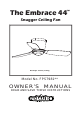
The Embrace 44 ™ Snugger Ceiling Fan Net Weight 23.68 lbs (10.74 kg) Model No.
Important Safety Instructions WARNING: To avoid fire, shock and serious personal injury, follow these instructions. 1. Read your owner’s manual and safety information before installing your new fan. Review the accompanying assembly diagrams. 2. Before servicing or cleaning unit, switch power off at service panel and lock service panel disconnecting means to prevent power from being switched on accidentally.
Table of Contents Unpacking Instructions . . . . . . . . . . . . . . . . . . . . . . . . . . . . . . . . . . . . . . . . . . . . . . . . . . . . . . . . . . . 4 Energy Efficient Use of Ceiling Fans . . . . . . . . . . . . . . . . . . . . . . . . . . . . . . . . . . . . . . . . . . . . . . . . 5 Electrical and Structural Requirements . . . . . . . . . . . . . . . . . . . . . . . . . . . . . . . . . . . . . . . . . . . . . . 5 How to Hang Your Ceiling Fan . . . . . . . . . . . . . . . . . . . . . . . . . . .
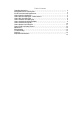
This manual is designed to make it as easy as possible for you to assemble, install, operate, and maintain your ceiling fan Tools Needed for Assembly Materials Wiring outlet box and box connectors must be of type required by local code. The minimum wire would be a 3conductor (2-wire with ground) of the following size: Three wire connectors (supplied) WARNING Before assembling your ceiling fan, refer to section on proper method of wiring your fan (page 8).
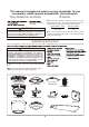
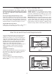
Energy Efficient Use of Ceiling Fans Ceiling fan performance and energy savings rely heavily on the proper installation and use of the ceiling fan. Here are a few tips to ensure efficient product performance. Using the Ceiling Fan Year Round Summer Season: Use the ceiling fan in the counterclockwise direction. The airflow produced by the ceiling fan creates a wind-chill effect, making you “feel” cooler. Select a fan speed that provides a comfortable breeze, lower speeds consume less energy.
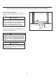
Electrical and Structural Requirements (Continued) Deep box with brace (Figure 3) Paired with a deep box, this hanger is meant to span between two joists and takes the place of wooden blocking. CEILING JOIST WARNING To reduce the risk of fire, electric shock, or personal injury, mount to outlet box marked acceptable for fan support of 15.88 kg (35 lbs) or less and use mounting screws provided with the outlet box.
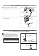
How to Hang Your Ceiling Fan WARNING Ceiling The fan must be hung with at least 7´ of clearance from floor to blades. (Figure 1) WARNING To avoid possible electrical shock, be sure electricity is turned off at the main fuse box before hanging. NOTE: If you are not sure if the outlet box is grounded, contact a licensed electrician for advice, as it must be grounded for safe operation.
How to Wire Your Ceiling Fan - Remote Control If you feel that you do not have enough electrical wiring knowledge or experience, have your fan installed by a licensed electrician. WARNING Remote Transmitter Unit Detail To avoid possible electrical shock, be sure electricity is turned off at the main fuse box before wiring. NOTE: If you are not sure if the outlet box is grounded, contact a licensed electrician for advice, as it must be grounded for safe operation. ON ECE ON ECE 1 1.
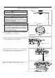
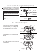
How to Assemble Your Ceiling Fan 1. Assemble the motor assembly to ceiling bracket assembly using the previously removed hex nuts and flat washers and securely tighten all hex nuts. (Figure 1) Ceiling Bracket Assembly Motor Assembly Figure 1 2. Assemble the housing to ceiling bracket assembly using the previously removed screws and securely tighten all screws. (Figure 2) Ceiling Bracket Assembly Housing Figure 2 How to Assemble the Ceiling Fan Blades 1.
How to Assemble the Ceiling Fan Blades (continued) 2. Secure the blade holders to the bottom of the motor assembly using the 1/4Ý-20 x 14 mm screws. (Figure 2) NOTE: Periodically check blade holder hardware and Motor Assembly resecure if necessary. ! WARNING To reduce the risk of personal injury, do not bend the blade holders when installing, balancing the blades or cleaning the fan. Do not insert foreign objects in between the rotating blades.
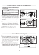
How to Assemble the Light Kit (continued) 4. Assemble the socket plate assembly to the light plate assembly using the previously removed screws. (Figure 4) Socket Plate Assembly Light Plate Assembly Figure 4 5 (Option A--for use with light kit) Insert light bulb into socket. (Figure 5A) CAUTION To reduce the risk of fire, use 100-watt max. type T4-minican JD E11 tungsten halogen bulb. Turn off the wall switch and allow the bulb to cool for 10 minutes before relamping. Bulb is pressurized and may shatter.
How to Install Your Remote Control (Option #1) 1. Unthread two screws from the wall switch plate. (Figure 1) 2. Install the control bracket with two #6-32x 3/4” screws. Push the four plastic plugs in to cover the screw holes. (Included in the control packaging). (Figure 2) Figure 1 Figure 2 How to Install Your Remote Control (Option #2) 1. Unthread two screws from the wall switch plate. (Figure 1) 2. Install the control bracket with two #6-32x 1” screws.
Trouble Shooting ʆWARNING For your own safety turn off power at fuse box or circuit breaker before trouble shooting your fan. Trouble 1. FAN WILL NOT START Probable Cause Suggested Remedy 1. Fuse or circuit breaker blown. 1. Check main and branch circuit fuses or circuit breakers. 2. Loose power line connections to the fan, or loose switch wire connections in the switch housing. 2. Check line wire connections to fan and switch wire connections in the switch housings.
Parts List Model #FPS7981** Ref.
FPS7981** Exploded-View 1 12 11 2 3 12 5 4 12 10 7 6 8 12 9 Figure 1 NOTE: 15
Copyright 2014 Fanimation 10983 Bennett Parkway Zionsville, IN 46077 Toll Free (888) 567-2055 FAX (866) 482-5215 Outside U.S. call (317) 733-4113 Visit Our Website www.fanimation.com 2014/02 V.
The Embrace ™ Ventilador de techo Peso neto 23.68 kg (10.74 lbs) Modelo N.
Instrucciones de seguridad importantes ADVERTENCIA: Siga estas instrucciones para prevenir incendios, descargas eléctricas y lesiones personales graves. 1. Lea el manual del propietario y la información de seguridad antes de instalar su nuevo ventilador. Observe los diagramas de ensamblaje adjuntos. 2. Antes de llevar a cabo el mantenimiento o la limpieza de la unidad, desconecte la electricidad en el panel de servicio y bloquee los medios de desconexión del mismo para evitar que se active accidentalmente.
GARANTÍA LIMITADA DE POR VIDA Se extiende al comprador original de un ventilador Fanimation 7. Fanimation se reserva el derecho de modificar o discontinuar un producto en cualquier momento, o sustituir cualquier pieza según lo establecido por esta garantía. 8. En ningún caso se podrá devolver un ventilador sin previa autorización por parte de Fanimation. Las devoluciones autorizadas deberán ir acompañadas del recibo de venta y deberán enviarse a Fanimation, previo pago del flete.
Este manual está diseñado para facilitar al máximo el ensamblaje, la instalación, el funcionamiento y el mantenimiento de su ventilador de techo. Herramientas necesarias para el ensamblaje Materiales L q ó ó g é y . má T q ñ xó ADVERTENCIA g m ñ A.W 12 Antes de ensamblar el ventilador de techo, consulte la sección sobre el método correcto de instalación eléctrica del ventilador (página 24).
8VR HÀFLHQWH GH OD HQHrJtD HQ vHQWLODGRrHV GH WHcho El nivel de rendimiento y ahorro de energía de los ventiladores de techo dependen de su correcta instalación yuso.Acontinuaciónlepresentamosalgunassugerencias para asegurar un rendimiento eficiente del producto. Uso del ventilador de techo todo el año En verano: Use el ventilador de techo en sentido contrario a las agujas del reloj. El flujo de aire que produce el ventilador creará un efecto frío del aire que lo refrescará más.
Requisitos eléctricos y estructurales (cont.) Profunda caja con aparato ortopédico (Figura 3) Conectado a una caja de distribución eléctrica, este colgador sirve para abarcar el espacio entre dos vigas y ocupar el lugar de bloqueo de la madera. Vigas del techo ADVERTENCIA Para reducir el riesgo de incendios, descargas eléctricas o lesiones personales, fije el ventilador a la caja de distribución eléctrica marcada como aceptable para soporte de ventilador de 15,88kg (35lb).
Cómo colgar el ventilador de techo ADVERTENCIA Techo Las aspas del ventilador deben estar suspendidas, al menos, a 2 m (7´) del piso (Figura 1) ADVERTENCIA Para evitar posibles descargas eléctricas, asegúrese de que la electricidad esté desconectada en la caja de fusibles principal antes de colgar el ventilador.
Cómo realizar la instalación eléctrica del ventilador de techo Si considera que no cuenta con la experiencia o los conocimientos eléctricos necesarios, contrate a un electricista autorizado para instalar el ventilador. ADVERTENCIA Detalle del transmisor remoto Para evitar posibles descargas eléctricas, asegúrese de que la electricidad esté desconectada en la caja de fusibles principal antes de realizar la instalación eléctrica.
Cómo realizar la instalación eléctrica del ventilador de techo (cont.) 1. Instale la unidad del motor a la unidad de soporte de techo utilizando las tuercas hexagonales y arandelas planas anteriormente extraídas y fíjelas adecuadamente. (Figura 1) Unidad de soporte del ventilador Unidad de motor Figura 1 2. Instale la carcasa a la unidad de soporte de techo utilizando los tornillos anteriormente extraídos y fíjelos adecuadamente.
Cómo ensamblar los Aspas (cont.) 2. )LMH ORV VRSRUWHV GH DVSDV DO VRSRUWH GHO PRWRU PHGLDQWH ORV WRUQLOORV GH [ PP D WUDYpV GH ORV RULILFLRV XELFDGRV DO FRVWDGR GHO VRSRUWH GHO PRWRU )LJXUD NOTA: Revise periódicamente las piezas de los soportes de las aspas y vuelva a ajustarlas si fuese necesario. ! Unidad del PRWRU Soporte de aspas ADVERTENCIA Para reducir el riesgo de lesiones personales, no doble los soportes de aspas al instalarlos, balancear las aspas o limpiar el ventilador.
Cómo ensamblar los kit de luz(cont.) 4 (Opción A – Para su uso con el kit de iluminación) PRECAUCIÓN Para reducir el riesgo de incendios, utilice la bombilla halógena tungsteno de tipo T4-minican JD E11 de 100 vatios máximo. Apague el interruptor de la pared y deje que la bombilla se enfríe durante 10 minutos antes de cambiar la bombilla. La bombilla está presurizada y puede hacerse añicos. NO TOQUE LA BOMBILA CON LAS MANOS SIN PROTECCIÓN.
Cómo instalar su mando a distancia (Opción #1) 1. Retire los dos tornillos colocados en la plaza del interruptor de la pared. (Figura 1) 2. Instale el soporte de control con los dos tornillos #6-32x 3/4”. Empuje los cuatro tapones de plástico para cubrir los orificios de los tornillos. (Incluidos con el mando). (Figura 2) Figura 1 Figura 2 Cómo instalar su mando a distancia (Opción #2) 1. Retire los dos tornillos colocados en la plaza del interruptor de la pared. (Figura 1) 2.
Solución de problemas ʆADVERTENCIA Para su propia seguridad, desconecte la electricidad de la caja de fusibles o disyuntor antes de solucionar problemas en su ventilador. Problema 1. EL VENTILADOR NO ARRANCA Causa posible Solución sugerida 1. El fusible o el disyuntor están fundidos. 1. Controle los fusibles del circuito principal y derivado o los disyuntores. 2. Las conexiones eléctricas del ventilador o del interruptor en la caja del interruptor están flojas. 2.
Lista de piezas Modelos N.° FPS7981** Reference Descripción Pieza # N.
FPS7981** Despiece 1 12 11 2 3 12 5 4 12 10 7 6 8 12 9 Figura 1 NOTA: la ilustración que se muestra no está hecha a 31
Copyright 2014 Fanimation 10983 Bennett Parkway Zionsville, IN 46077 Llame sin cargo al (888) 567-2055 FAX (866) 482-5215 Desde fuera de los EE.UU., llame al (317) 733-4113 Visite nuestro sitio Web en www.fanimation.com 2014/02 V.