DUPLEX™ CEILING FAN MODEL #FPD6254GR Español p. 21 ATTACH YOUR RECEIPT HERE AND REGISTER YOUR FAN AT FANIMATION.COM READ AND SAVE THESE INSTRUCTIONS Purchase Date Net Weight 16.09 lbs (7.3 kg) Questions, problems, missing parts? Before returning to your retailer, call our customer service department at 1-888-567-2055, 8 a.m.-5 p.m., EST, Monday-Friday.
Important Safety Instructions WARNING: To avoid fire, shock and serious personal injury, follow these instructions. 1. Read your owner’s manual and safety information before installing your new fan. Review the accompanying assembly diagrams. 2. Before servicing or cleaning unit, switch power off at service panel and lock service panel disconnecting means to prevent power from being switched on accidentally.
Table of Contents Unpacking Instructions. . . . . . . . . . . . . . . . . . . . . . . . . . . 4 Energy Efficient Use of Ceiling Fans . . . . . . . . . . . . . . . . 5 Electrical and Structural Requirements. . . . . . . . . . . . . . 5 How to Assemble Your Ceiling Fan. . . . . . . . . . . . . . . . . 7 How to Hang Your Ceiling Fan . . . . . . . . . . . . . . . . . . . . . 9 How to Wire Your Ceiling Fan . . . . . . . . . . . . . . . . . . . . . 10 How to Install Your Canopy Housing . . . . . . . . . . . . . .
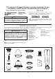
This manual is designed to make it as easy as possible for you to assemble, install, operate, and maintain your ceiling fan Tools Needed for Assembly blade screwdriver Materials Wiring outlet box and box connectors must be of type required by local code. The minimum wire would be a 3conductor (2-wire with ground) of the following size: Four wire connectors (supplied) WARNING Before assembling your ceiling fan, refer to section on proper method of wiring your fan (page 10).
Energy Efficient Use of Ceiling Fans Ceiling fan performance and energy savings rely heavily on the proper installation and use of the ceiling fan. Here are a few tips to ensure efficient product performance. Using the Ceiling Fan Year Round Summer Season: Use the ceiling fan in the counterclockwise direction. The airflow produced by the ceiling fan creates a wind-chill effect, making you “feel” cooler.
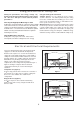
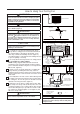
Electrical and Structural Requirements (Continued) Deep box with brace (Figure 3) Paired with a deep box, this hanger is meant to span between two joists and takes the place of wooden blocking. CEILING JOIST WARNING To reduce the risk of fire, electric shock, or personal injury, mount to outlet box marked acceptable for fan support of 15.9 kg (35 lbs) or less and use mounting screws provided with the outlet box.
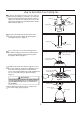
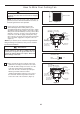
How to Assemble Your Ceiling Fan 1. Remove the hanger ball portion from the downrod/ hanger ball assembly by loosening the set screw in the hanger ball until the ball falls freely down the downrod. Remove the pin from the downrod, then remove the hanger ball. Retain the pin and hanger ball for reinstallation in Step 6. (Figure 1) Pin Downrod Set Screw Hanger Ball Figure 1 2. Remove the hairpin clip and clevis pin from the bottom of the downrod. Retain the pin and clip for reinstallation in Step 4.
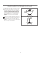
How to Assemble Your Ceiling Fan (continued) 6. Reinstall the hanger ball on the downrod as follows. Route the black, white, blue wires and safety cable through the hanger ball. Position the pin through the two holes in the downrod and align the hanger ball so the pin is captured in the groove in the top of the hanger ball. Pull the hanger ball up tight against the pin. Securely tighten the set screw in the hanger ball. A loose set screw could create fan wobble. (Figure 6) Figure 6 7.
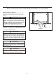
How to Hang Your Ceiling Fan WARNING To avoid possible electrical shock, be sure electricity is turned off at the main fuse box before hanging. (Figure 1) NOTE: If you are not sure if the outlet box is grounded, contact a licensed electrician for advice, as it must be grounded for safe operation. /#+0 (75' $1: WARNING Figure 1 The fan must be hung with at least 7´ of clearance from floor to blades. (Figure 2) %'+.+0) WARNING 01 .
How to Wire Your Ceiling Fan WARNING To avoid possible electrical shock, be sure electricity is turned off at the main fuse box before hanging (Figure 1). MAIN FUSE BOX NOTE: If you are not sure if the outlet box is grounded, contact a licensed electrician for advice, as it must be grounded for safe operation. Figure 1 1.
How to Install Your Canopy Housing NOTE: This step is applicable after the neccessary wiring is completed. 1. Remove one of the two shoulder screws in the hanger bracket. Loosen the second shoulder screw without fully removing it. Assemble canopy by rotating key slot in canopy over shoulder screw in hanger bracket. Tighten shoulder screw. Fully assemble and tighten second shoulder screw that was previously removed.
How to Assemble Your Ceiling Fan Blades (Continued) 3. Assemble the blade holder cover to bottom of the motor assembly using the previously removed screws and securely tighten all six screws. (Figure 3) Motor Assembly Blade Holder Cover Figure 3 How to Assemble Your Light Kit 1. Remove one of the three screws in the adaptor plate at the bottom of the motor assembly and retain the screw for later. Slightly loosen the remaining two screws. (Figure 1) Motor Assembly Figure 1 2.
How to Assemble Your Light Kit (continued) 4. Connect the 2 pin connectors from the LED assembly to the 2 pin connectors from motor assembly. (Figure 4) CAUTION Motor Assembly To reduce the risk of electric shock, disconnect the electrical supply circult to the fan before installing light kit. LED Assembly Figure 4 5. Assemble the LED assembly to the light plate assembly using the screws removed in Step 3 and securely tighten all two screws.
How to Operate Your Ceiling Fan 1. IMPORTANT: Using a full range dimmer switch (not included) to control fan speed will damage the fan. To reduce the risk of fire or electrical shock, do not use a full range dimmer switch to control the fan speed. (Figure 1) 2. Restore electrical power to the outlet box by turning the electricity on at the main fuse box.
How to Operate Your Ceiling Fan (continued) 6. Remote Control Setting and Speed (RPM) Setting Process : (Figure 4) 1) After installing and wiring the unit, restore power to your fan by ensuring that the breaker and wall switch that controls the power supply is moved to the on position, press and hold the “SET” button inside of the battery compartment of the handheld remote control for 1-5 seconds. 2) You must press the “SET” button within 60 seconds of restoring power to the fan.
How to Operate Your Ceiling Fan (continued) 9. If you have encountered an issue during the set up process, you can follow the below procedure to clean the memory code of your handheld remote: (Figure 7) 1) Turn the wall switch that controls the power to the fan to the off position, or the breaker that controls the power to the fan to the off position. 2) Turn the wall switch that controls the power to the fan to the on position, or the breaker that controls the power to the fan to the on position.
Parts List Model #FPD6254GR Ref.
Duplex ™ Model FPD6254GR Exploded-View Illustration 1 14 2 3 4 5 13 6 14 7 8 9 12 10 11 NOTE: The illustration shown is not to scale or its actual con guration may vary. Product/parts are subject to change without notice.
Trouble Shooting ! WARNING For your own safety, turn off power at fuse box or circuit breaker before trouble shooting your fan. Some suggested remedies require the attention of a licensed electrician. Trouble Probable Cause 1. Fuse or circuit breaker blown. 1.FAN WILL NOT START 2. Loose power line connections to the fan, or loose switch wire connections in the switch housing. 3. Reversing switch in neutral position. 2.FAN SOUNDS NOISY Suggested Remedy 1.
10983 Bennett Parkway Zionsville, IN 46077 Phone: 888-567-2055 Outside U.S.: 317-733-4113 FAX: 866-482-5215 FANIMATION.COM 2018/03 V.
VENTILADOR DE TECHO DUPLEX™ MODELO #FPD6254GR ADJUNTE SU RECIBO AQUÍ Y REGISTRE SU VENTILADOR EN FANIMATION.COM LEA Y GUARDE ESTAS INSTRUCCIONES Fecha de compra Peso neto 7.3 kg (16.09 lbs) Preguntas, problemas, piezas faltantes? Antes de volver a la tienda, llame a nuestro Departamento de Servicio al Cliente al 1-888-567-2055, 8 a.m. - 5 pm, hora del Este, de lunes - viernes.
Instrucciones de seguridad importantes ADVERTENCIA: Siga estas instrucciones para prevenir incendios, descargas eléctricas y lesiones personales graves. 1. Lea el manual del propietario y la información de seguridad antes de instalar su nuevo ventilador. Observe los diagramas de ensamblaje adjuntos. 2. Antes de llevar a cabo el mantenimiento o la limpieza de la unidad, desconecte la electricidad en el panel de servicio y bloquee los medios de desconexión del mismo para evitar que se active accidentalmente.
GARANTÍA LIMITADA DE POR VIDA Se extiende al comprador original de un ventilador Fanimation 5. Debido a las diversas condiciones climáticas, esta garantía no cubre cambios en la terminación, incluidos oxidación, corrosión, falta de brillo o peladuras. 6. Esta garantía es nula y no se aplica a daños por instalación incorrecta, negligencia, accidentes, uso indebido, exposición al calor o a la humedad en exceso, o como resultado de cualquier modificación realizada al producto original. 7.
Este manual está diseñado para facilitar al máximo el ensamblaje, la instalación, el funcionamiento y el mantenimiento de su ventilador de techo. Herramientas necesarias para el ensamblaje • Destornillador Phillips • Escalera de tijera • Destornillador de ¼˝ Materiales La caja de distribución eléctrica y los conectores de la caja deben ser del tipo requerido por el código local.
Uso eficiente de la energía en ventiladores de techo El nivel de rendimiento y ahorro de energía de los ventiladores de techo dependen de su correcta instalación yuso.Acontinuaciónlepresentamosalgunassugerencias para asegurar un rendimiento eficiente del producto. Uso del ventilador de techo todo el año En verano: Use el ventilador de techo en sentido contrario a las agujas del reloj. El flujo de aire que produce el ventilador creará un efecto frío del aire que lo refrescará más.
Requisitos eléctricos y estructurales (cont.) Profunda caja con aparato ortopédico (Figura 3) Conectado a una caja de distribución eléctrica, este colgador sirve para abarcar el espacio entre dos vigas y ocupar el lugar de bloqueo de la madera.
Cómo ensamblar el ventilador de techo 1. Extraiga la pieza de la bola colgante de la unidad de la bola colgante / varilla aflojando el tornillo de presión de la bola colgante hasta que la bola se libere de la varilla. Retire el pasador del barral y luego extraiga la semiesfera. Conserve el pasador y la semiesfera para su reinstalación en el Paso 6 (Figura 1). Pasador Bola para colgar Tornillo de fijación Ranura de la bola colgante Figura 1 2 Retire .
Cómo ensamblar el ventilador de techo (cont.) 6. Vuelva a colocar la semiesfera en el barral como se indica a continuación. Pase los tres cables de cables de blanco, negro y azul cable de soporte para techo a través de la semiesfera. Pase el pasador a través de los dos orificios en el barral y alinee la semiesfera de modo que el pasador quede atrapado en la ranura de la parte superior de la misma. Empuje la semiesfera hacia arriba, bien ajustada contra el pasador.
Cómo colgar el ventilador de techo ADVERTENCIA Para evitar una posible descarga eléctrica, asegúrese de cortar la alimentación eléctrica de la caja de fusibles principal antes de colgar el ventilador. (Figura 1) NOTA: Si no está seguro de si la caja de salida tiene conexión a tierra, pida consejo a un electricista certificado, ya que debe tener conexión a tierra para un funcionamiento seguro.
Cómo realizar la instalación eléctrica del ventilador de techo ADVERTENCIA Para evitar una posible descarga eléctrica, asegúrese de cortar la alimentación eléctrica de la caja de fusibles principal antes de colgar el ventilador. (Figura 1) 24+0%+2#. %#,# &' (75+$.'5 NOTA: Si no está seguro de si la caja de salida tiene conexión a tierra, pida consejo a un electricista certificado, ya que debe tener conexión a tierra para un funcionamiento seguro. Figura 1 1.
Cómo instalar la carcasa de la cubierta NOTA: Este paso se debe realizar luego de completar la instalación eléctrica necesaria. 1. Retire uno de los dos tornillos de reborde de la abrazadera para colgar. Afloje el segundo tornillo de reborde sin retirarlo del todo. Ensamble la base girando el chavetero de la base sobre el tornillo de reborde de la abrazadera para colgar. Ajuste el tornillo de reborde. Ensamble por completo el segundo tornillo de reborde que antes había retirado y ajústelo.
Cómo ensamblar las aspas del ventilador de techo (cont.) 3. Instale la cubierta del soporte de pala en la parte inferior del motor usando los tornillos extraídos anteriormente y fije los seis tornillos adecuadamente. (Figura 3) Motor Cubierta del soporte de pala Figura 3 Cómo ensamblar su el kit de iluminación 1. Retire uno de los tres tornillos en la placa del adaptador en la parte inferior del ensamble del motor. y guárdelos para después. Afloje ligeramente los dos tornillos restantes.
Cómo ensamblar su el kit de iluminación (cont.) 4. Instale el conector de 2 clavijas desde unidad de luz LED conexión a la unidad del motor. (Figura 4) PRECAUCIÓN Motor A fin de reducir el riesgo descargas eléctricas, desconecte el circuito de suministro eléctrico al ventilador antes de instalar el kit de iluminación. Unidad de luz LED Figura 4 5. Instale la unidad LED en la ernsamble de la placa de iluminación mediante los dos tornillos.
Cómo utilizar su ventilador de techo 1. El uso de un regulador de la intensidad completa (no incluido) para controlar la velocidad del ventilador dañará el dispositivo. Para reducir el riesgo de incendio o descarga eléctrica, no utilice dicho regulador para controlar la velocidad del ventilador. (Figura 1) 2. Restaure la fuente de alimentación de la toma de corriente enciendo la electricidad del fusible principal.
Cómo utilizar su ventilador de techo (cont.) 6. Configuración del mando a distancia y proceso de configuración de la velocidad (RPM): (Figura 4) 1) Tras la instalación y el cableado de la unidad, vuelva a suministrar electricidad a su ventilador asegurándose de que el disyuntor y el interruptor de pared que controlan la fuente de alimentación estén en la posición de encendido. Pulse y mantenga pulsado el botón “SET” del interior del compartimento de las pilas del mando a distancia durante 1-5 segundos.
Cómo utilizar su ventilador de techo (Cont.) 8. Conmutador “D” y “ON”: La selección “ON” es la selección regulable de luz y debe ser utilizada con todas las bombillas menos con las bombillas CFL. La selección “D” es la encender solo la luz (sin la función de regulación) y debe ser utilizada con bombillas CFL, ya que estas no pueden ser reguladas.
Lista de piezas Modelos N.° FPD6254GR N.° de Ref. Descripción Pieza # N.
Duplex™ Model FPD6254GR Ilustración del despiece 1 14 2 3 4 5 13 6 14 7 8 9 12 14 10 11 NOTA: OD LOXVWUDFLyQ TXH VH PXHVWUD QR HVWi KHFKD D HV FDOD \ VX FRQ¿JXUDFLyQ UHDO SXHGH YDULDU 38
Solución de problemas ʆADVERTENCIA Para su propia seguridad, desconecte la electricidad de la caja de fusibles o disyuntor antes de solucionar problemas en su ventilador. Problema 1. EL VENTILADOR NO ARRANCA Causa posible Solución sugerida 1. El fusible o el disyuntor están fundidos. 1. Controle los fusibles del circuito principal y derivado o los disyuntores. 2. Las conexiones eléctricas del ventilador o del interruptor en la caja del interruptor están flojas. 2.
10983 Bennett Parkway Zionsville, IN 46077 Llame sin cargo al (888) 567-2055 FAX (866) 482-5215 Desde fuera de los EE.UU., llame al (317) 733-4113 Visite nuestro sitio Web en www.fanimation.com 2018/03 V.