CELANO v2™ CEILING FAN MODEL #FP8062B** Español p. 20 ATTACH YOUR RECEIPT HERE AND REGISTER YOUR FAN AT FANIMATION.COM READ AND SAVE THESE INSTRUCTIONS Serial Number Purchase Date Net Weight 17.86 . lbs (8.10 kgs) Questions, problems, missing parts? Before returning to your retailer, call our customer service department at 1-888-567-2055, 8 a.m.-5 p.m., EST, Monday-Friday.
Important Safety Instructions WARNING: To avoid fire, shock and serious personal injury, follow these instructions. 1. Read your owner’s manual and safety information before installing your new fan. Review the accompanying assembly diagrams. 2. Before servicing or cleaning unit, switch power off at service panel and lock service panel disconnecting means to prevent power from being switched on accidentally.
Table of Contents Unpacking Instructions. . . . . . . . . . . . . . . . . . . . . . . . . . . 4 Energy Efficient Use of Ceiling Fans . . . . . . . . . . . . . . . . 5 Electrical and Structural Requirements. . . . . . . . . . . . . . 5 How to Assemble Your Ceiling Fan Blades . . . . . . . . . . . 7 How to Assemble Your Ceiling Fan. . . . . . . . . . . . . . . . . 8 How to Hang Your Ceiling Fan . . . . . . . . . . . . . . . . . . . . 10 How to Wire Your Ceiling Fan . . . . . . . . . . . . . . . . . . . . .
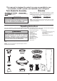
This manual is designed to make it as easy as possible for you to assemble, install, operate, and maintain your ceiling fan Tools Needed for Assembly blade screwdriver Materials Wiring outlet box and box connectors must be of type required by local code. The minimum wire would be a 3conductor (2-wire with ground) of the following size: Four wire connectors Installed Wire Length Up to 50 ft. 50 - 100 ft.
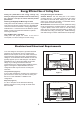
Energy Efficient Use of Ceiling Fans Ceiling fan performance and energy savings rely heavily on the proper installation and use of the ceiling fan. Here are a few tips to ensure efficient product performance. Choosing the Appropriate Mounting Location Ceiling fans should be installed, or mounted, in the middle of the room and at least 7 feet from floor to the blade and 18 inches from wall to the blade. If ceiling height allows, install the fan 8 - 9 feet from floor to the blade for optimal airflow.
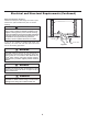
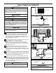
Electrical and Structural Requirements (Continued) Deep box with brace (Figure 3) Paired with a deep box, this hanger is meant to span between two joists and takes the place of wooden blocking. CEILING JOIST WARNING To reduce the risk of fire, electric shock, or personal injury, mount to outlet box marked acceptable for fan support of 15.9 kg (35 lbs) or less and use mounting screws provided with the outlet box.
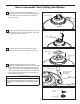
How to Assemble Your Ceiling Fan Blades 1. Remove the two preassembled screws of the downrod support from the motor assembly then retain the screws for How to Assemble Your Ceiling Fan, Step 4. (Figure 1) Downrod Support Motor Assembly Figure 1 2. Remove the six preassembled screws of the motor coupler washer from the motor assembly, then retain the screws for Step 6. (Figure 2) Motor Coupler Washer Figure 2 3. Remove the motor coupler washer and upper housing cover from the motor assembly.
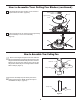
How to Assemble Your Ceiling Fan Blades (continued) 5. Re-assemble the upper housing cover and motor coupler washer as shown. (Figure 5) Motor Coupler Washer Upper Housing Cover Figure 5 6. Securely tighten the six screws that were previously removed in Step 2 on the motor assembly. (Figure 6) Figure 6 How to Assemble Your Ceiling Fan 1. Remove the hanger ball portion from the downrod/ hanger ball assembly by loosening the set screw in the hanger ball until the ball falls freely down the downrod.
How to Assemble Your Ceiling Fan (continued) 3. Route the black, white and blue wires and safety cable through the downrod. (Figure 3) Black, White, Blue wires and Safety Cable Figure 3 4. Slide downrod into the downrod support on top of the motor. Install the clevis pin by aligning the holes in the downrod support with holes in the downrod. Secure clevis pin with hairpin clip. Tighten the two set screws with nuts in the downrod support.
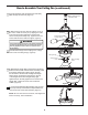
How to Hang Your Ceiling Fan WARNING To avoid possible electrical shock, be sure electricity is turned off at the main fuse box before hanging. (Figure 1) NOTE: If you are not sure if the outlet box is grounded, contact a licensed electrician for advice, as it must be grounded for safe operation. MAIN FUSE BOX Figure 1 WARNING The fan must be hung with at least 7´ of clearance from floor to blades.
How to Wire Your Ceiling Fan NOTE: The remote unit has 32 different code combinations. To prevent possible interference from or to other remote units, simply change the combination code in the remote and receiver. Receiver Unit ON 1. To set the code on receiver unit, slide dip switches to the same positions as set on the remote. (Figure 1) 1 NOTE: Factory setting is all up. Do not use this position.
How to Wire Your Ceiling Fan (continued) 4. Once the connection has been made, slide the receiver into the hanger bracket, taking care not to pinch the wires. (Figure 5) Receiver Hanger Bracket Figure 5 Installing Your Canopy Housing NOTE: This step is applicable after the neccessary wiring is completed. 1. Remove one of the two shoulder screws in the hanger bracket. Loosen the second shoulder screw without fully removing it.
How to Assemble Your Light Kit CAUTION To reduce the risk of electric shock, disconnect the electrical supply circuit to the fan before installing your light kit. 1. Remove one of the three screws in the support bracket at the bottom of the motor assembly and retain the screw for later. Slightly loosen the remaining two screws. Assemble the light plate assembly to the motor assembly support bracket using the two key slots in the light plate assembly.
How to Operate Your Ceiling Fan 1. IMPORTANT: Using a full range dimmer switch (not included) to control fan speed will damage the fan. To reduce the risk of fire or electrical shock, do not use a full range dimmer switch to control the fan speed. (Figure 1) 2. Restore electrical power to the outlet box by turning the electricity on at the main fuse box.
How to Operate Your Ceiling Fan (continued) 6. If airflow is desired in the opposite direction, turn the fan off and wait for the blades to stop turning. Then slide the reverse switch on top of motor assembly to the opposite position and turn fan on again. (Figure 6) Reverse Switch Information Season Summer Winter Rotation Direction Counter-Clockwise Clockwise Reversing Switch Switch Position Left Right Figure 6 How to Install Your Remote Control 1.
Parts List Model #FP8062B** Ref.
Celano v2 ™ Model FP8062B** Exploded-View Illustration 1 2 3 4 5 6 7 8 10 11 12 9 NOTE: The illustration shown is not to scale or its actual con guration may vary. Product/parts are subject to change without notice.
Trouble Shooting ! WARNING For your own safety, turn off power at fuse box or circuit breaker before trouble shooting your fan. Some suggested remedies require the attention of a licensed electrician. Trouble Probable Cause 1. Fuse or circuit breaker blown. 1.FAN WILL NOT START 2. Loose power line connections to the fan, or loose switch wire connections in the switch housing. 3. Reversing switch in neutral position. 2.FAN SOUNDS NOISY Suggested Remedy 1.
10983 Bennett Parkway Zionsville, IN 46077 Phone: 888-567-2055 Outside U.S.: 317-733-4113 FAX: 866-482-5215 FANIMATION.COM 2019/01 V.
VENTILADOR DE TECHO CELANO v2 ™ MODELO #FP8062B** ADJUNTE SU RECIBO AQUÍ Y REGISTRE SU VENTILADOR EN FANIMATION.COM LEA Y GUARDE ESTAS INSTRUCCIONES Número de serie Fecha de compra Peso neto 8.10 kgs (17.86 lbs) Preguntas, problemas, piezas faltantes? Antes de volver a la tienda, llame a nuestro Departamento de Servicio al Cliente al 1-888-567-2055, 8 a.m. - 5 pm, hora del Este, de lunes - viernes.
Instrucciones de seguridad importantes ADVERTENCIA: Siga estas instrucciones para prevenir incendios, descargas eléctricas y lesiones personales graves. 1. Lea el manual del propietario y la información de seguridad antes de instalar su nuevo ventilador. Observe los diagramas de ensamblaje adjuntos. 2. Antes de llevar a cabo el mantenimiento o la limpieza de la unidad, desconecte la electricidad en el panel de servicio y bloquee los medios de desconexión del mismo para evitar que se active accidentalmente.
GARANTÍA LIMITADA DE POR VIDA Se extiende al comprador original de un ventilador Fanimation 4. Debido a las diversas condiciones climáticas, esta garantía no cubre cambios en la terminación, incluidos oxidación, corrosión, falta de brillo o peladuras. 5. Esta garantía es nula y no se aplica a daños por instalación incorrecta, negligencia, accidentes, uso indebido, exposición al calor o a la humedad en exceso, o como resultado de cualquier modificación realizada al producto original. 6.
Instrucciones para el desempaque Para su comodidad, marque cada uno de los pasos. A medida que completa cada paso, coloque una marca de verificación. Con esto se asegurará de completar todos los pasos y podrá saber desde dónde retomar si fuera interrumpido. ADVERTENCIA No instale o utilice el ventilador si falta alguna pieza o si hay piezas dañadas. Este producto está diseñado para ser usado sólo con las piezas suministradas o los accesorios indicados por Fanimation específicamente para el mismo.
r v r cho Uso del ventilador de techo todo el año El nivel de rendimiento y ahorro de energía de los ventiladores de techo dependen de su correcta instalación yuso.Acontinuaciónlepresentamosalgunassugerencias para asegurar un rendimiento eficiente del producto. En verano: Use el ventilador de techo en sentido contrario a las agujas del reloj. El flujo de aire que produce el ventilador creará un efecto frío del aire que lo refrescará más.
Requisitos eléctricos y estructurales (cont.) Uso del soporte (Figura 3) Conectado a una caja de distribución eléctrica, este colgador sirve para abarcar el espacio entre dos vigas y ocupar el lugar de bloqueo de la madera. Vigas del techo ADVERTENCIA Para reducir el riesgo de incendios, descargas eléctricas o lesiones personales, fije el ventilador a la caja de distribución eléctrica marcada como aceptable para soporte de ventilador de 15,88kg (35lb).
Cómo ensamblar las aspas del ventilador de techo 1. Retire los dos tornillos preensamblados del soporte de la varilla del ensamble del motor y guárdelos para volverlos a instalar en la Cómo ensamblar el ventilador de techo, paso 4. Soporte de la varilla Motor Figura 1 2. Retire los seis tornillos preensamblados de la arandela del acoplador del motor del ensamble del motor y guárdelos para volverlos a instalar en el paso 6. (Figura 2) Arandela del acoplador del motor Figura 2 3.
Cómo ensamblar las aspas del ventilador de techo (cont.) 5. Vuelva a ensamblar la cubierta de la carcasa y la arandela del acoplador del motor, como se muestra. (Figura 5) Arandela del acoplador del motor Cubierta de la carcasa superior Figura 5 6. Apriete firmemente los seis tornillos que se retiraron en el paso 2 en el ensamble del motor. (Figura 6) Figura 6 Cómo ensamblar el ventilador de techo 1.
Cómo ensamblar el ventilador de techo (cont.) 3. Lntroduzca los cables de color negro, blanco y azu cables y cable de seguridad a través de la varilla. (Figura 3) Negro, Blanco y Azul Cables y cable de seguridad 4. Coloque el soporte de la varilla y alinee los orificios de la clavija de horquilla en ambas piezas. Instale la clavija de horquilla y asegúrela con la pinza de horquilla. Fije los dos tornillos de presión y las tuercas de seguridad en el soporte de la varilla interior.
Cómo colgar el ventilador de techo ADVERTENCIA Para evitar una posible descarga eléctrica, asegúrese de cortar la alimentación eléctrica de la caja de fusiblesprincipal antes de colgar el ventilador. (Figura 1) PRINCIPAL CAJA DE FUSIBLES NOTA: Si no está seguro de si la caja de salida tiene conexión a tierra, pida consejo a un electricista certificado, ya que debe tener conexión a tierra para un funcionamiento seguro.
Cómo colgar el ventilador de techo (cont.) 4. Levante cuidadosamente el ventilador y coloque el ensamble de la bola para colgar/varilla en la abrazadera para colgar que acaba de fijar a la caja de salida. Asegúrese de que la ranura de la bola esté alineada con la lengüeta de la abrazadera para colgar. (Figura 4) 5. Fije el cable de seguridad al cable de soporte para techo. Deslice la abrazadera de cables por el cable de seguridad (del ventilador).
Cómo realizar la instalación eléctrica del ventilador de techo NOTA: El mando a distancia incluido en este ventilador tiene 32 combinaciones diferentes de códigos. Para evitar posibles interferencias desde o hacia otros mandos a distancia, modifique el código de combinación de su transmisor y receptor. Unidad del receptor ON 1 1. Para configurar el código de unidad del receptor. Deslice los interruptores de código a las mismas posiciones que en el transmisor.
Cómo realizar la instalación eléctrica del ventilador de techo (cont.) 3. Una vez realizadas las conexiones, gire los conductores hacia arriba y, con cuidado, colóquelos dentro de la caja de salida; con los conductores blancos y verdes hacia un lado y los conductores negros hacia el otro.
Cómo ensamblar las kit de luz PRECAUCIÓN A fin de reducir el riesgo descargas eléctricas, desconecte el circuito de suministro eléctrico al ventilador antes de instalar el kit de iluminación. ATTENTION Ensamble de la placa de iluminación Pour réduire le risque d'électrocution, débranchez le circuit d'alimentation électrique du ventilateur avant d'installer le kit d'éclairage. 1.
Cómo utilizar su control remoto de mano 1. El uso de un regulador de la intensidad completa (no incluido) para controlar la velocidad del ventilador dañará el dispositivo. Para reducir el riesgo de incendio o descarga eléctrica, no utilice dicho regulador para controlar la velocidad del ventilador. (Figura 1) 2. Restaure la fuente de alimentación de la toma de corriente enciendo la electricidad del fusible principal.
Cómo utilizar su ventilador de techo (cont.) 5. Funciones del control remoto: (Figura 5) Luz LED del indicador: Velocidad del ventilador Enciende el ventilador y aumenta la velocidad. Enciende el ventilador y disminuye la velocidad. Enciende el ventilador y aumenta la velocidad. Temporizador de apagado automático: Pulse y tanto el ventilador y la iluminación se apagarán tras 1 hora. Pulse y tanto el ventilador y la iluminación se apagarán tras 3 hora.
Mantenimiento El único mantenimiento necesario para el ventilador de techo es una limpieza periódica. Al llevar a cabo la limpieza, use sólo un cepillo suave o un paño sin pelusas, para evitar rayar el acabado. No se requieren agentes abrasivos de limpieza; los mismos deben evitarse para prevenir daños en el acabado. PRECAUCIÓN No utilice solventes para limpiar el ventilador de techo. Podrían dañar el motor o las aspas y ocasionar posibles descargas eléctricas.
Lista de piezas Modelo N.° FP8062B** N.° de Ref. Descripción Pieza N.
Celano v2 ™ Model FP8062B** Ilustración del despiece 1 2 3 4 5 6 7 8 10 11 12 9 NOTA: la ilustración que se muestra no está hecha a es cala y su configuración real puede variar.
Solución de problemas ▲ADVERTENCIA Para su propia seguridad, desconecte la electricidad de la caja de fusibles o disyuntor antes de solucionar problemas en su ventilador. ▲AVERTISSEMENT Pour votre sécurité, placez le coffret à fusibles ou le disjoncteur hors tension avant de tenter d’identifier tout problème pouvant affecter votre ventilateur. Problema 1. EL VENTILADOR NO ARRANCA Causa posible Solución sugerida 1. El fusible o el disyuntor están fundidos. 1.
10983 Bennett Parkway Zionsville, IN 46077 Llame sin cargo al (888) 567-2055 FAX (866) 482-5215 Desde fuera de los EE.UU., llame al (317) 733-4113 Visite nuestro sitio Web en www.fanimation.com 2019/01 V.