
Owner's Manual


9
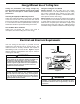
Switch Cup/Adapter or Light kit Installation
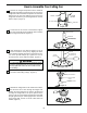
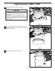
1a. Remove the three screws from cover-switch cup
assembly. (Figure 19a)
1b. Remove the three screws from light kit assembly.
(Figure 19b)
Figure 19a Figure 19b
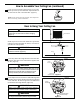
2. Remove one of the three screws in the support
bracket. Slightly loosen the remaining two screws.
Assemble the adapter assembly to the hous ing support
. y l bmessa r e t pada eh t n i s t o l s yek owt eh t gn i su t ekcar b
ee r h t l l a ne t hg i t y l e r uces dna we r cs d r i h t eh t eca l peR
screws. (Figure 20)
Figure 20
SCREWS (3)
ADAPTER
ASSEMBLY
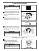
3a. Securely attach the 9-pin switch cup connector to
the wiring harness socket within the adapter assembly.
(Figura 12a)
Figure 21a
ADAPTER
ASSEMBLY
3b. <<FP8016** ONLY>> Connect the 2-pin
connector from the light kit assembly
connector from the motor assembly.
to the 2-pin
(Figure 21b)
Figure 21b
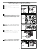
4. Install the housing switch cup onto the assembled
adapter with the three screws removed in step 1.
(Figure 22)
Figure 22
FP8012** FP80016**
FP8012** FP80016**
LIGHT KIT ASSEMBLY
Cover-Switch Cup
ASSEMBLY
LIGHT KIT
ASSEMBLY