™ The Xeno Ceiling Fan Net Weight: 22.67 lbs (10.29 kgs) Model No.
Important Safety Instructions WARNING: To avoid fire, shock and serious personal injury, follow these instructions. 1. Read your owner’s manual and safety information before installing your new fan. Review the accompanying assembly diagrams. 2. Before servicing or cleaning unit, switch power off at service panel and lock service panel disconnecting means to prevent power from being switched on accidentally.
Table of Contents Unpacking Instructions. . . . . . . . . . . . . . . . . . . . . . . . . . . 4 Energy Efficient Use of Ceiling Fans . . . . . . . . . . . . . . . . 5 Electrical and Structural Requirements. . . . . . . . . . . . . . 5 How to Assemble Your Ceiling Fan. . . . . . . . . . . . . . . . . 7 How to Hang Your Ceiling Fan . . . . . . . . . . . . . . . . . . . . . 7 How to Wire Your Ceiling Fan . . . . . . . . . . . . . . . . . . . . . . 8 Installing the Canopy Housing . . . . . . . . . . . . . . . .
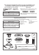
This manual is designed to make it as easy as possible for you to assemble, install, operate, and maintain your ceiling fan Tools Needed for Assembly blade screwdriver Materials Wiring outlet box and box connectors must be of type required by local code. The minimum wire would be a 3conductor (2-wire with ground) of the following size: Four wire connectors (supplied) WARNING Before assembling your ceiling fan, refer to section on proper method of wiring your fan (page 8).
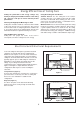
Energy Efficient Use of Ceiling Fans Ceiling fan performance and energy savings rely heavily on the proper installation and use of the ceiling fan. Here are a few tips to ensure efficient product performance. Choosing the Appropriate Mounting Location Ceiling fans should be installed, or mounted, in the middle of the room and at least 7 feet above the floor and 18 inches from the walls. If ceiling height allows, install the fan 8 - 9 feet above the floor for optimal airflow.
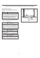
Electrical and Structural Requirements (Continued) Deep box with brace (Figure 3) Paired with a deep box, this hanger is meant to span between two joists and takes the place of wooden blocking. CEILING JOIST WARNING To reduce the risk of fire, electric shock, or personal injury, mount to outlet box marked acceptable for fan support of 15.9 kg (35 lbs) or less and use mounting screws provided with the outlet box.
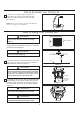
How to Assemble Your Ceiling Fan 1. Cut off excess lead wire approximately 6 to 9 inches above top of the top of the downrod. Strip insulation off 1/2 inch from the end of each lead wire. (Figure 1) NOTE: All set screws must be checked, and retightened where necessary, before installation. Figure 1 How to Hang Your Ceiling Fan WARNING To avoid possible ſre or shock, be sure electricity is turned off at the main fuse box before hanging.
How to Wire Your Ceiling Fan NOTE: If fan or supply wires are different colors than indicated, haYH WKLV XQLW LQVWDOOHG E\ D TXDOL¿HG HOHFWULFLDQ WARNING To avoid possible electrical shock, be sure electricity is turned off at the main fuse box before wiring (Figure 1). MAIN FUSE BOX NOTE: If you are not sure if the outlet box is grounded, contact a licensed electrician for advice, as LW PXVW EH JURXQGHG IRU VDIH RSHUDWLRQ Figure 1 CAUTION: INCORRECT WIRE CONNECTION COULD DAMAGE THIS RECEIVER.
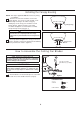
Installing the Canopy Housing NOTE: This step is applicable after the neccessary wiring is completed. 1. Remove one of the two shoulder screws in the hanger bracket. Loosen the second shoulder screw without fully removing it. Assemble canopy by rotating key slot in canopy over shoulder screw in hanger bracket. Tighten shoulder screw. Fully assemble and tighten second shoulder screw that was previously removed.
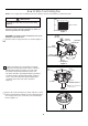
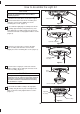
How to Assemble the Light Kit CAUTION To Reduce The Risk Of Electric Shock, Disconnect The Electrical Supply Circuit To The Fan Before Installing Light Kit. 1. Remove one of the three screws in the support bracket at the bottom of the motor assembly and retain the screw for later. Slightly loosen the remaining two screws. (Figure 1) Motor Assembly Figure 1 2. Assemble the light plage assembly to the motor assembly support bracket using the two key slots in the light plate assembly.
How to Assemble the Light Kit (continued) 6. Secure the glass to the LED assembly by twisting in a clockwise direction. Do not over-tighten. (Figure 6) LED Assembly Glass Figure 6 How to Operate Your Remote Control 1. IMPORTANT: Using a full range dimmer switch (not included) to control fan speed will damage the fan. To reduce the risk of fire or electrical shock, do not use a full range dimmer switch to control the fan speed. (Figure 1) 2.
How to Operate Your Remote Control (continued) 4. Pairing Process for Receiver & Transmitter: (Figure 4) – The receiver and accompanying transmitter are matched at the factory. If replacing transmitter or receiver, you must follow the pairing process below before using the unit. The fanSync receiver can be paired to up to five (5) transmitters. NOTE: Smart device pairing is unlimited.
How to Install Your Remote Control 1. Installing Wall Plate: (Figure 1) Attach wall plate using the two provided screws. Figure 1 Maintenance CAUTION 1. Periodic cleaning of your new ceiling fan is the only maintenance that is needed. When cleaning, use only a soft brush or lint free cloth to avoid scratching the finish. Abrasive cleaning agents are not required and should be avoided to prevent damage to finish. Do not use solvents when cleaning your ceiling fan.
Parts List Model #FP6728** Ref.
FP6728** Exploded-View Illustration 1 2a 2b 2c 2d 2 2e 3 4 5 6 7 8 NOTE: The illustration shown is not to scale or its actual parts configuration may var.
Trouble Shooting ! WARNING For your own safety, turn off power at fuse box or circuit breaker before trouble shooting your fan. Some suggested remedies require the attention of a licensed electrician. Trouble Probable Cause 1. Fuse or circuit breaker blown. 1.FAN WILL NOT START 2. Loose power line connections to the fan, or loose switch wire connections in the switch housing. 3. Reversing switch in neutral position. 2.FAN SOUNDS NOISY Suggested Remedy 1.
Copyright 2015 Fanimation 10983 Bennett Parkway Zionsville, IN 46077 (888) 567-2055 FAX (866) 482-5215 Outside U.S. call (317) 733-4113 Visit Our Website @ www.fanimation.com 2015/08 V.
™ The Xeno Ventilador de techo Peso neto 10.29 kgs (22.67 lbs) Modelo N.
Instrucciones de seguridad importantes ADVERTENCIA: Siga estas instrucciones para prevenir incendios, descargas eléctricas y lesiones personales graves. 1. Lea el manual del propietario y la información de seguridad antes de instalar su nuevo ventilador. Observe los diagramas de ensamblaje adjuntos. 2. Antes de llevar a cabo el mantenimiento o la limpieza de la unidad, desconecte la electricidad en el panel de servicio y bloquee los medios de desconexión del mismo para evitar que se active accidentalmente.
GARANTÍA LIMITADA DE POR VIDA Se extiende al comprador original de un ventilador Fanimation 5. Debido a las diversas condiciones climáticas, esta garantía no cubre cambios en la terminación, incluidos oxidación, corrosión, falta de brillo o peladuras. 6. Esta garantía es nula y no se aplica a daños por instalación incorrecta, negligencia, accidentes, uso indebido, exposición al calor o a la humedad en exceso, o como resultado de cualquier modificación realizada al producto original. 7.
Este manual está diseñado para facilitar al máximo el ensamblaje, la instalación, el funcionamiento y el mantenimiento de su ventilador de techo. Herramientas necesarias para el ensamblaje • Destornillador Phillips • Escalera de tijera • Destornillador de ¼˝ Materiales • Pelacables • Tres conectores de cables (incluidos) ADVERTENCIA Antes de ensamblar el ventilador de techo, consulte la sección sobre el método correcto de instalación eléctrica del ventilador (página 25).
Uso eficiente de la energía en ventiladores de techo El nivel de rendimiento y ahorro de energía de los ventiladores de techo dependen de su correcta instalación yuso.Acontinuaciónlepresentamosalgunassugerencias para asegurar un rendimiento eficiente del producto. Uso del ventilador de techo todo el año En verano: Use el ventilador de techo en sentido contrario a las agujas del reloj. El flujo de aire que produce el ventilador creará un efecto frío del aire que lo refrescará más.
Requisitos eléctricos y estructurales (cont.) Profunda caja con aparato ortopédico (Figura 3) Conectado a una caja de distribución eléctrica, este colgador sirve para abarcar el espacio entre dos vigas y ocupar el lugar de bloqueo de la madera.
Cómo ensamblar el ventilador de techo 15, 2 22, 4 cm a 86 cm 1. Corte el exceso de cable aproximadamente de 15 a 23 cm (6 a 9 pulgadas) por encima de la parte en cada extremo del cable. (Figura 1) NOTA: Se deben revisar todos los tornillos de fijación y volver a ajustarlos cuando sea necesario antes de realizar la instalación.
Cómo realizar la instalación eléctrica del ventilador de techo NOTA: Si los cables de suministro o del ventilador son de colores difHUHQWHV TXH ORV LQGLFDGRV FRQWUDWH D XQ HOHFWULFLVWD FDOL¿FDGR para que realice la instalación. ADVERTENCIA Para evitar una posible descarga eléctrica, asegúrese de cortar la alimentación eléctrica de la caja de fusibles principal antes de alambrado el ventilador.
Cómo instalar la carcasa de la cubierta NOTA: Este paso se debe realizar luego de completar la instalación eléctrica necesaria. 1. Retire uno de los dos tornillos de reborde de la abrazadera para colgar. Afloje el segundo tornillo de reborde sin retirarlo del todo. Ensamble la base girando el chavetero de la base sobre el tornillo de reborde de la abrazadera para colgar. Ajuste el tornillo de reborde. Ensamble por completo el segundo tornillo de reborde que antes había retirado y ajústelo.
Cómo ensamblar las kit de luz PRECAUCIÓN Para reducir el riesgo de incendios o descargas eléctricas, desconecte el circuito de alimentación eléctrica al ventilador antes de instalar el kit de luz. Unidad del motor 1. Extraiga uno de los tres tornillos del soporte ubicado en la parte inferior de la unidad del motor y guarde los tornillos para pasos posteriores. Afloje levemente los otros dos tornillos. (Figura 1) Figura 1 2.
Cómo ensamblar las kit de luz (cont.) 6. Asegure el vidrio en al unidad de luz LED girándolo en el sentido de las agujas del reloj y sin apretar demasiado. (Figura 6) Unidad de luz LED Vidrio Figura 6 Cómo utilizar su control remoto de mano 1. IMPORTANTE: El uso de un regulador de la intensidad completa (no incluido) para controlar la velocidad del ventilador dañará el dispositivo.
Cómo utilizar su control remoto de mano (cont.) 4. Proceso de emparejamiento del Recepctor y Transmisor: (Figura 4) – El receptor y el transmisor que lo acompaña están emparejados de fábrica. Si sustituye el transmisor o el receptor, debe seguir el siguiente proceso antes de poder usar la unidad. El receptor fanSync puede emparejarse con hasta (5) transmisores. NOTA: El emparejamiento de dispositivos inteligentes es ilimitado.
Cómo instalar su mando a distancia 1. Instalación de la placa de la pared: (Figura 1) Fije la placa de la pared usando los dos tornillos suministrados. Figura 1 Mantenimiento El único mantenimiento necesario para el ventilador de techo es una limpieza periódica. Al llevar a cabo la limpieza, use sólo un cepillo suave o un paño sin pelusas, para evitar rayar el acabado. No se requieren agentes abrasivos de limpieza; los mismos deben evitarse para prevenir daños en el acabado.
Lista de piezas Modelo N.° FP6728** N.° de Ref. Descripción Pieza N.
FP6728** Ilustración del despiece 1 2a 2b 2c 2d 2 2e 3 4 5 6 7 8 Figura 1 NOTA: La ilustración que se muestra no está hecha a escala y su c 32 guración real y/o terminación puede variar
Solución de problemas ʆADVERTENCIA Para su propia seguridad, desconecte la electricidad de la caja de fusibles o disyuntor antes de solucionar problemas en su ventilador. Problema 1. EL VENTILADOR NO ARRANCA Causa posible Solución sugerida 1. El fusible o el disyuntor están fundidos. 1. Controle los fusibles del circuito principal y derivado o los disyuntores. 2. Las conexiones eléctricas del ventilador o del interruptor en la caja del interruptor están flojas. 2.
Copyright 2015 Fanimation 10983 Bennett Parkway Zionsville, IN 46077 Llame sin cargo al (888) 567-2055 FAX (866) 482-5215 Desde fuera de los EE.UU., llame al (317) 733-4113 Visite nuestro sitio Web en www.fanimation.com 2015/08 V.