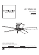
ASH™ CEILING FAN MODEL #LP8365LBI Español p. 16 ITEM #0747616 ATTACH YOUR RECEIPT HERE READ AND SAVE THESE INSTRUCTIONS Serial Number Purchase Date Net Weight 14.47 lbs (6.57 kg) Questions, problems, missing parts? Before returning to your retailer, call our customer service department at 1-888-567-2055, 8 a.m.-5 p.m., EST, Monday-Friday.
Important Safety Instructions WARNING: To avoid fire, shock and serious personal injury, follow these instructions. 1. Read your owner’s manual and safety information before installing your new fan. Review the accompanying assembly diagrams. 2. Before servicing or cleaning unit, switch power off at service panel and lock service panel disconnecting means to prevent power from being switched on accidentally.
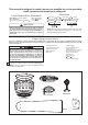
This manual is designed to make it as easy as possible for you to assemble, install, operate and maintain your ceiling fan Materials Tools Needed for Assembly Ŗ ne hillips head screwdriver Ŗ One stepladder Ŗ hree wire connectors supplied ! Ŗ One wire stripper Ŗ One lade screwdriver iring outlet o and o connectors ust e of type re uired y the local code he ini u wire would e a conductor wire with ground of the following si e: nstalled ire ength p to ft ft WARNING Before assembling your ceiling fan, refe
Energy Efficient Use of Ceiling Fans Ceiling fan performance and energy savings rely heavily on the proper installation and use of the ceiling fan. Here are a few tips to ensure efficient product performance. Using the Ceiling Fan Year Round Summer Season: Use the ceiling fan in the counterclockwise direction. The airflow produced by the ceiling fan creates a wind-chill effect, making you “feel” cooler. Select a fan speed that provides a comfortable breeze, lower speeds consume less energy.
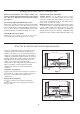
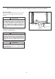
Electrical and Structural Requirements (Continued) Brace use (Figure 3) Paired with a deep box, this hanger is meant to span between two joists and takes the place of wooden blocking. CEILING JOIST WARNING To reduce the risk of fire, electrical shock, or personal injury, mount fan to outlet box marked acceptable for fan support of 15.88 kg (35 lbs) or less. Use screws supplied with outlet box.
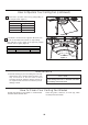
How to Hang Your Ceiling Fan WARNING Ceiling The fan must be hung with at least 7´ of clearance from floor to blades. (Figure 1) WARNING To avoid possible electrical shock, be sure electricity is turned off at the main fuse box before hanging. NOTE: If you are not sure if the outlet box is grounded, contact a licensed electrician for advice, as it must be grounded for safe operation.
How to Wire Your Ceiling Fan 1. Connect the green grounding lead from the ceiling bracket and motor assembly to the supply grounding conductor (this may be a bare wire or wire with green colored insulation). Securely connect wires with a wire connector. Securely connect the white wire (coming from fan) to the white supply (neutral) wire using a wire connector. Securely connect the black wire (coming from fan) to the black supply wire using a wire connector.
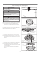
How to Assemble the Ceiling Fan Blades (continued) 2. Remove and discard the motor stops from the motor assembly by removing the screws. (Figure 2) Motor Assembly Motor Stops Figure 2 3. Secure the blade holders to the bottom of the motor assembly using the 1/4Ý-20 screws. (Figure 3) NOTE: Periodically check blade holder hardware and resecure if necessary.
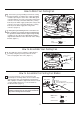
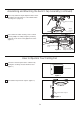
Assembling and Mounting the Switch Cap Assembly (continued) 4. Securely attach the 9-pin adapter from the motor assembly to the wire harness socket within switch housing cover. (Figure 4) Motor Assembly Switch Housing Cover Figure 4 5. Assemble the switch housing cover to switch housing adapter assembly using the previously removed screws and securely tighten all screws. (Figure 5) Switch Housing Cover Figure 5 Switch Housing Adapter Assembly How to Operate Your Ceiling Fan 1.
How to Operate Your Ceiling Fan (continued) 3. Check the operation of the fan by gently pulling on the fan pull chain. (Figure 3) Fan Pull Chain Operating Sequence 1st Pull High 2 Pull 3rd Pull Medium 4th Pull Off nd Low Figure 3 4. If airflow is desired in the opposite direction, turn the fan off and wait for the blades to stop turning. Then slide the reverse switch to the opposite position and turn fan on again.
Trouble Shooting WARNING For your own safety turn off power at fuse box or circuit breaker before trouble shooting your fan. Trouble Probable Cause 1. Fuse or circuit breaker blown. 1.FAN WILL NOT START 2. Loose power line connections to the fan, or loose switch wire connections in the switch housing. 3. Reversing switch in neutral position. 1. Blades not attached to fan. 2. Loose screws in motor housing. 2.FAN SOUNDS NOISY 3. Screws securing fan blade holders to motor flywheel are loose. 4.
Parts List Model No.
ASH™ Model LP8365LBI Exploded-View Illustration 1 2 6 3 4 6 5 6 6 Figure 1 NOTE: The illustration shown is not to scale or its actual con guration may vary. Product/parts are subject to change without notice.
10983 Bennett Parkway Zionsville, IN 46077 Phone: 888-567-2055 Outside U.S.: 317-733-4113 FAX: 866-482-5215 www.fanimation.com 2015/11 V.
VENTILADOR DE TECHO ASH ™ MODEL #LP8365LBI ARTÍCULO #0747616 Adjunte su recibo AQUÍ LEA Y GUARDE ESTAS INSTRUCCIONES Número de serie Fecha de compra Peso neto 6.57 kg (14.47 lbs) Preguntas, problemas, piezas faltantes? Antes de volver a la tienda, llame a nuestro Departamento de Servicio al Cliente al 1-888-567-2055, 8 a.m. - 5 pm, hora del Este, de lunes - viernes.
Instrucciones importantes de seguridad ADVERTENCIA: siga estas instrucciones para prevenir incendios, descargas eléctricas y lesiones personales graves. 1. Lea el manual del propietario y la información de seguridad antes de instalar su nuevo ventilador. Observe los diagramas de ensamblaje adjuntos. 2. Antes de llevar a cabo el mantenimiento o la limpieza de la unidad, desconecte la electricidad en el panel de servicio y bloquee los medios de desconexión del mismo para evitar que se active accidentalmente.
Este manual está diseñado para facilitar al máximo el ensamblaje, la instalación, el funcionamiento y el mantenimiento de su ventilador de techo. Herramientas necesarias para el ensamblaje Destornillador Phillips Escalera de tijera Destornillador de ¼ Materiales La caja de distribución eléctrica y los conectores de la caja deben ser del tipo requerido por el código local.
r v El nivel de rendimiento y ahorro de energía de los ventiladores de techo dependen de su correcta instalación yuso.Acontinuaciónlepresentamosalgunassugerencias para asegurar un rendimiento eficiente del producto. r cho Uso del ventilador de techo todo el año En verano: Use el ventilador de techo en sentido contrario a las agujas del reloj. El flujo de aire que produce el ventilador creará un efecto frío del aire que lo refrescará más.
Requisitos eléctricos y estructurales (cont.) Uso del soporte (Figura 3) Conectado a una caja de distribución eléctrica, este colgador sirve para abarcar el espacio entre dos vigas y ocupar el lugar de bloqueo de la madera. Vigas del techo ADVERTENCIA Para reducir el riesgo de incendios, descargas eléctricas o lesiones personales, fije el ventilador a la caja de distribución eléctrica marcada como aceptable para soporte de ventilador de 15,88kg (35lb).
Cómo colgar el ventilador de techo ADVERTENCIA Techo Las aspas del ventilador deben estar suspendidas, al menos, a 2 m (7´) del piso (Figura 1) ADVERTENCIA 2m (7 pies) como mínimo Para evitar posibles descargas eléctricas, asegúrese de que la electricidad esté desconectada en la caja de fusibles principal antes de colgar el ventilador.
Cómo realizar la instalación eléctrica del ventilador de techo 1. Conecte el cable verde de la toma de tierra desde el soporte de techo al conductor de toma de tierra de la fuente y motor de alimentación (éste puede ser un cable pelado o un cable verde con aislamiento). Conecte los cables con cuidado usando un conector de cables. Conecte con cuidado el cable (que viene del ventilador) con el cable blanco (neutro) de la fuente de alimentación utilizando un conector de cables.
Cómo ensamblar las aspas de techo (Cont.) 2. Retire y deseche los topes del motor del ensamble del motor quitando los tornillos. (Figura 2) Motor Motor del ensamble Figura 2 3. -20 (Figura 3) NOTA: Revise periódicamente las piezas de los soportes de las aspas y vuelva a ajustarlas si fuese necesario. ! Tornillos de 1/4Ý-20 ADVERTENCIA Soporte de aspas Figura 3 Para reducir el riesgo de lesiones personales, no doble los soportes de aspas al instalarlos, balancear las aspas o limpiar el ventilador.
Instalación y montaje de la unidad de la copa del interruptor (Cont.) 4. Fije adecuadamente el adaptador de 9 pines desde el motor a la sujeción del arnés del cable ubicado dentro de la carcasa de la cubierta del interruptor. (Figura 4) Motor Carcasa de la cubierta del interruptor Figura 4 5. Instale la carcasa de la cubierta del interruptor en el adaptador de la cubierta del interruptor usando los tornillos extraídos anteriormente y fíjelos adecuadamente.
Cómo utilizar su ventilador de techo (Cont.) 3. Verifique el funcionamiento del ventilador tirando levemente de la cadena de encendido/apagado para el control de la velocidad. (Figura 3) Secuencia de funcionamiento de la cadena del tirador 1.ª tirada Alta 2.ª tirada Media 3.ª tirada Baja 4.ª tirada Apagado Figura 3 4. Si desea que el flujo de aire se desplace en la dirección opuesta, apague el ventilador y espere a que las aspas se detengan.
Solución de problemas ADVERTENCIA Para su propia seguridad, desconecte la electricidad de la caja de fusibles o disyuntor antes de solucionar problemas en su ventilador. Problema 1. EL VENTILADOR NO ARRANCA Causa posible Solución sugerida 1. El fusible o el disyuntor están fundidos. 1. Controle los fusibles del circuito principal y derivado o los disyuntores. 2. Las conexiones eléctricas del ventilador o del interruptor en la caja del interruptor están flojas. 2.
Lista de piezas Modelos N.° LP8365LBI N.° de Ref. Descripción Pieza # N.
ASH™ Modelo N.
10983 Bennett Parkway Zionsville, IN 46077 Llame Sin Cargo al: 888-567-2055 Desde fuera de los EE.UU. llame al : 317-733-4113 FAX: 866-482-5215 www.fanimation.com 2015/11 V.