
Use and Care Guide

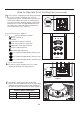
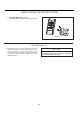

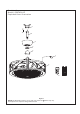


Figure 2
MAIN FUSE BOX
How to Operate Your Ceiling Fan
2. Restore electrical power to the outlet box by turning
the electricity on at the main fuse box. (Figure 2)
Check to see that all connections are tight, including
ground, and that no bare wire is visible at the wire
connectors, except for the ground wire. Do not
operate fan until the blades are in place. Noise and
fan damage could result.
WARNING
NOTE:
The fan's receiver features an automatic learning
function. There are no frequency switches on the receiver
unit. The receiver will automatically scan the frequency
from the hand held control if any changes are made.
The frequency settings should only be changed in the
case of interference or if multiple ceiling fans with the
same type of control system are installed in the same
structure.
3. To make fan operational, install 23A/12V battery
(included) in hand-held remote transmitter, with fan
power off. Then follow the remote code setting process.
(If not used for long periods of time, remove battery to
prevent damage to transmitter). Store the remote away
from excessive heat or humidly. (Figure 3)
1. IMPORTANT: Using a full range dimmer switch
(not included) to control fan speed will damage the fan.
To reduce the risk of fire or electrical shock, do not use
a full range dimmer switch to control the fan speed.
(Figure 1)
Figure 1
For illustrative purposes only-not
intended to cover all types of controls
11
How to Install Your Canopy Housing
2. Securely attach and tighten the canopy screw cover
over the shoulder screws in the hanger bracket utilizing
the keyslot twist-lock feature. (Figure 2)
1. Remove one of the two shoulder screws in the
hanger bracket. Loosen the second shoulder screw
without fully removing it. Assemble canopy by
rotating key slot in canopy over shoulder screw in
hanger bracket. Tighten shoulder screw. Fully
assemble and tighten second shoulder screw that
was previously removed. (Figure 1)
WARNING
To avoid possible fire or shock, make sure that the
electrical wires are completely inside the canopy
housing and not pinched between the housing and the
ceiling.
NOTE: This step is applicable after the neccessary wiring is completed.
Canopy
Figure 1
Canopy Screw
Cover
Figure 2
12V 23A
Battery (1 pcs)
Figure 3
WARNING
Do not operate this fan with a variable (Rheostat) wall
controller or dimmer switch. Doing so could result in
damage to the ceiling fan's remote control unit.