
User's Manual
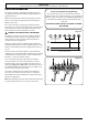
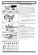
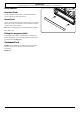
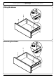
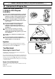
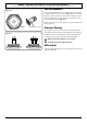
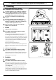
Table Of Contents
- U111301 cover - Falcon
- U111301-01 [AUS]
- 1. Before you start...
- 2. Cooker Overview
- 3. Rotary clock
- 4. Cooking Tips
- 5. Cooking Table
- 6. Cleaning Your Cooker
- 7. Troubleshooting
- 8. Service and Spares
- 9. Installation
- Safety Requirements and Regulations
- Provision of Ventilation
- Location of Cooker
- Conversion
- Positioning the Cooker
- Moving the Cooker
- Completing the Move
- Levelling the Cooker
- Fitting the Stability Bracket and Chain
- Repositioning the Cooker Following Connection
- Conversion to Another Gas
- Gas Connection
- Natural Gas
- Propane
- Pressure Testing
- Electrical Connection
- Connection in New Zealand
- Final Checks
- Customer Care
- Fitting the drawer
- Removing the drawer
- 10. Conversion to Propane Gas
- 11. Servicing
- 12. Circuit Diagram
- 13. Technical Data

WARNING – SERVICING TO BE CARRIED OUT ONLY BY AN AUTHORISED PERSON
Disconnect from electricity and gas before servicing. Check appliance is safe when you have nished.
34
A
B
ArtNo.311-0010 Injectors
Conversion from Natural Gas
(1.0 kPa) to LPG X Propane
(2.54 kPa)
n
This conversion must be performed by a competent
person, in accordance with these instructions and
with the local supply company requirements. Read
the instructions before converting this appliance.
n
Failure to convert the appliance correctly could
invalidate any warranty or liability claims and lead
to prosecution.
n
The conversion instructions must be used in
conjunction with the rest of the appliance
instruction, in particular for information on
Standards, cooker positioning, connection, hose
suitability, etc.
n
When servicing or replacing gas-carrying
components, disconnect from the gas before
starting, and check that the appliance is gas sound
after completion.
n
DO NOT use reconditioned or unauthorised gas
controls.
n
Disconnect from the electricity supply before
conversion. Before electrical reconnection, check
that the appliance is electrically safe.
Injectors
Remove the burner caps and heads. Remove the old jets.
Fit the new jets: see ‘Technical Data’ section for correct jets.
Reassemble in the reverse order (Fig. 10.1).
Tap Adjustment
Removing the Control Panel
Pull o all the control knobs. Remove the 3 xing screws
underneath the control panel.
The control panel will drop down slightly. It is held at the top
by two holes in the top edge, one at each end, that locate on
the tags on the inner panel (Fig. 10.2). Lift the control panel
clear of the tags and pull forwards, taking care not to damage
or strain the wiring.
Bypass Screw Adjustment
Turn the bypass screw on each control clockwise to the stop
(Fig. 10.3).
Ret the control panel.
ArtNo.0102-0011 - Screwing
the control valve bypass screw
10. Conversion to Propane Gas
Fig. 10.1
Fig. 10.2
Fig. 10.3
A – Jet, B – Jet