USER GUIDE & INSTALLATION INSTRUCTIONS Professional+ 100 FX Dual Fuel Australia U111130 - 03
Contents 1. 2. Before you start... 1 9.
1. Before you start... Your cooker should give you many years of trouble-free cooking if installed and operated correctly. It is important that you read this section before you start. • The cooker should not be placed on a base. • This appliance is designed for domestic cooking only. Use for any other purpose could invalidate any warranty or liability claim. • Before operating the oven(s) please refer to the oven shelf installation, in the Accessories section.
• Always keep combustible materials, e.g. curtains, and flammable liquids a safe distance away from the cooker. • Make sure that the gas supply is turned on and that the cooker is wired in and switched on. • DO NOT spray aerosols in the vicinity of the cooker while it is on. • In your own interest and that of safety, it is law that all gas appliances be installed by a qualified person(s). • An appliance for use on LPG must not be installed in a room or internal space below ground level, e.g.
Ventilation • The use of a cooking appliance results in the production of heat and moisture in the room in which it is installed. Therefore, make sure that the kitchen is well ventilated: keep natural ventilation holes open or install a powered cookerhood that vents outside. If you have several hotplates/burners on, or use the cooker for a long time, open a window or turn on an extractor fan : Unattended cooking on a n WARNING hob with fat or oil can be dangerous and may result in fire.
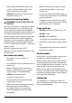
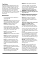
Fig. 1.1 • DO NOT modify this appliance. This appliance is not intended to be operated by means of external timer or separated remote-control system. • If flammable materials are stored in the drawer, oven(s) or grill(s) it may explode and result in fire or property damage. ArtNo.062-0003 - 90SC - Prof+ steam burst Oven Care • When the oven is not in use and before attempting to clean the cooker always be certain that the control knobs are in the OFF position.
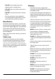
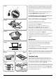
• DO NOT use the timed oven if the adjoining oven is already warm. • DO NOT place warm food in the oven to be timed. • DO NOT use a timed oven that is already warm. • Use dry oven gloves when applicable – using damp gloves might result in steam burns when you touch a hot surface. Cleaning Oven Shelves To remove and refit the shelves. Pull the shelf forwards until the back of the shelf is stopped by the shelf support (Fig. 1.2).
6 • NEVER store flammable materials in the drawer. This includes paper, plastic and cloth items, such as cookbooks, plastic ware and towels, as well as flammable liquids. • DO NOT store explosives, such as aerosol cans, on or near the appliance. • DO NOT use steel wool, oven cleaning pads, or any other materials that will scratch the surface. • DO NOT attempt to disassemble or clean around any burner while another burner is on, otherwise an electric shock could result.
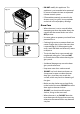
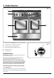
2. Cooker Overview Fig. 2.1 A B Professional + 100 FX C D E ArtNo.270-0029 - Prof+ 90SC annotated The 100 dual fuel cooker (Fig. 2.1) has the following features: A. 5 hotplate burners including a wok burner B. A control panel incorporating a timer C. Main (programmable) multifunction oven D. Multifunction oven E. Storage drawer ArtNo.270-0001 Proplus control to high Hotplate Burners The drawing by each of the control knobs indicates which burner that knob controls.
Fig. 2.3 If, when you let go of the control knob, the burner goes out, then the FSD has not been bypassed. Turn the control knob to the ‘OFF’ position and wait for one minute before you try again, this time making sure to hold in the control knob for slightly longer. ArtNo.270-0003 Proplus control to low Adjust the flame height to suit by turning the knob counterclockwise (Fig. 2.3). On this cooker the low position is beyond high, NOT between high and off.
The Griddle Plate Fig. 2.11 The griddle plate fits the left-hand pan support, front to back (Fig. 2.11). It is designed for cooking food on directly. DO NOT use pans of any kind on it. The griddle plate surface is non-stick and metal cooking utensils (e.g. spatulas) will damage the surface. Use heat resistant plastic or wooden utensils. n DO NOT put it crossways – it will not fit properly and will be unstable (Fig. 2.12).
Left-hand Multifunction Oven Modes The Multifunction Ovens Function Use Both ovens are multifunction ovens. Defrost To thaw small items in the oven without heat Fan oven A full cooking function, even heat throughout, great for baking In addition to the element around the fan, the left-hand oven is fitted with extra heating elements, in the top of the oven and under the oven base. Take care to avoid touching the top elements when placing or removing items from the oven.
Fanned Grilling This function operates the fan while the top element is on. It produces a more even, less fierce heat than a conventional grill. For best results place the food to be grilled on the pan provided. Thick pieces of meat or fish are ideal for cooking in this way, as the circulated air reduces the fierceness of the heat from the grill. The oven door should be kept closed while cooking is in progress, so saving energy.
The Ovens Fig. 2.15 The clock must be set to the time of day before the lefthand oven will work. See the following section on ‘The Clock’ for instructions on setting the time of day. The clock only controls the left-hand oven. ArtNo.270-0026 Proplus MF oven controls (2) References to ‘left-hand’ and ‘right-hand’ ovens apply as viewed from the front of the appliance. Note: Please remember that all cookers vary so temperatures in your new ovens may differ to those in your previous cooker.
Accessories Fig. 2.17 Oven Shelves – Left-hand (Main) Oven The left-hand oven is supplied with two flat shelves (Fig. 2.17). The oven shelves are retained when pulled forward but can be easily removed and refitted. To refit the shelf, line up the shelf with a groove in the oven shelf supports and push the shelf back until the ends hit the shelf stop. Lift up the front so the shelf ends clear the shelf stops, and then lower the front so that the shelf is level and push it fully back (Fig. 2.18). Fig. 2.
3. 2 Button - rotary clock Fig. 3.1 The clock must be set to the time of day before the main, programmable oven will work. ArtNo.300-0005 2BC minute minder setting C Setting the Clock D A B 1. Once the cooker is connected and switched on, the display will start to flash. 2. To set the time, turn the Timer (A) knob to the Clock (C) setting and back to the Manual (D) position. The centre dot will flash indicating the time can be set.
To stop the oven at a specific time of day Fig. 3.5 You have set the required temperature and function mode and you would like the oven to automatically stop. TOP TIP G Make a note of the current time so you do not forget. 1. A B Turn the Timer (A) knob to the Stop Time (G) setting. ‘AUTO’ will show in the display (Fig. 3.5). 2. Turn the Adjusting (B) knob to the amount of cooking time required. The display will show the current time plus the additional cooking time you have set (Fig. 3.6). 3.
To start and stop the oven automatically Fig. 3.9 The timer allows you to automatically start and stop by a combination of the length of the cooking time and the stop time. Giving you the flexibility to cook casseroles etc while you are out. You cannot set the actual start time. F A B Fig. 3.10 G A B 1. Turn the Timer (A) knob to the Cook Time (F) setting. Turn the Adjusting (B) knob clockwise to set the length of the cooking time required (Fig. 3.9). 2.
4. Cooking Tips Cooking with a Multifunction Oven General Oven Tips Remember: not all modes are suitable for all food types. The oven cooking times given are intended for a guide only. The wire shelves should always be pushed firmly to the back of the oven. Tips on Cooking with the Timer Baking trays with food cooking on them should be placed level with the front edge of the oven’s wire shelves. Other containers should be placed centrally.
5. Cooking Table The oven control settings and cooking times given in the table below are intended to be used AS A GUIDE ONLY. Individual tastes may require the temperature to be altered to provide a preferred result. Food is cooked at lower temperature in a fan oven than in a conventional oven. When using recipes, reduce the fan oven temperature by 10 °C and the cooking time by 5-10 minutes. The temperature in the fanned oven does not vary with height in the oven so you can use any shelf.
6. Cleaning Your Cooker Essential Information n n C NEVER use paint solvents, washing soda, caustic cleaners, biological powders, bleach, chlorine based bleach cleaners, coarse abrasives or salt. B DO NOT mix different cleaning products – they may react together with hazardous results. E D All parts of the cooker can be cleaned with hot soapy water – but take care that no surplus water seeps into the appliance. ArtNo.
Control Panel and Doors Fig. 6.5 Avoid using any abrasive cleaners including cream cleaners. For best results, use a liquid detergent. The same cleaner can be used on the doors, or alternatively, using a soft cloth wrung out in clean hot soapy water – but take care that no surplus water seeps into the appliance. After cleaning, polish with a dry cloth. Removing the Left-hand Main Oven Linings Fig. 6.6 Some of the lining panels can be removed for cleaning.
Cleaning Table Cleaners listed (Table 6.1) are available from supermarkets or electrical retailers as stated. For enamelled surfaces use a cleaner that is approved for use on vitreous enamel. Regular cleaning is recommended. For easier cleaning, wipe up any spillages immediately. Hotplate Part Finish Recommended Cleaning Method Hob top (including burner heads and caps) Enamel, stainless steel, aluminium Hot soapy water, soft cloth. Any stubborn stains remove gently with a nylon scourer.
7. Troubleshooting If there is an installation problem and I don’t get my original installer to come back to fix it who pays? You do. Service organisations will charge for their call outs if they are correcting work carried out by your original installer. It is in your interest to track down your original installer. Hotplate ignition or hotplate burners faulty Is the power on? Is the clock illuminated? If not, there maybe something wrong with the power supply.
The timed oven is not coming on when automatic cooking Has the oven knob been left in the OFF position by mistake? Fig. 7.1 Fig. 7.2 Oven temperature getting hotter as the cooker gets older If turning the temperature down using the oven control knob has not worked, or has only worked for a short time, then you may need a new thermostat. This should be fitted by a service person. Oven lights are not working The bulb has probably burnt out.
INSTALLATION Check the appliance is electrically safe when you have finished. 8. Service and Spares Firstly, please complete the appliance details below and keep them safe for future reference – this information will enable us to accurately identify the particular appliance and help us to help you. Filling this in now will save time and inconvenience if you later have a problem with the appliance. It may also be of benefit to keep your purchase receipt with this leaflet.
INSTALLATION Check the appliance is electrically safe and gas sound when you have finished. 9. Installation Safety Requirements and Regulations Provision of Ventilation You must be aware of the following safety requirements & regulations. This appliance is not connected to a combustion products evacuation device. Particular attention shall be given to the relevant requirements regarding ventilation.
INSTALLATION Check the appliance is electrically safe and gas sound when you have finished. 3 pan supports You will need the following equipment to complete the cooker installation satisfactorily: Griddle (Supplied) • Stability bracket: If the cooker is to be supplied with gas through a flexible hose, a stability bracket or chain MUST be fitted. • Gas pressure tester/manometer. • Flexible gas hose: Must be in accordance with the relevant standards. • Multimeter: For electrical checks.
INSTALLATION Check the appliance is electrically safe and gas sound when you have finished. Positioning the Cooker Fig. 9.1 The diagram (Fig. 9.1) shows the minimum recommended distance from the cooker to nearby surfaces as given in AS/NZS 5601. Where the appliance is installed next to cabinetry, the cabinet material must be capable of withstanding 70°C. If this appliance is installed near vinyl wrapped surfaces, use an installation kit available from the vinyl-wrap supplier.
INSTALLATION Check the appliance is electrically safe and gas sound when you have finished. Moving the Cooker Fig. 9.2 n On no account try and move the cooker while it is plugged into the electricity supply. n The cooker is very heavy, so take great care. We recommend that two people manoeuvre the cooker. Make sure that the floor covering is firmly fixed, or removed, to prevent it being disturbed when moving the cooker around.
INSTALLATION Check the appliance is electrically safe and gas sound when you have finished. Fitting the Stability Bracket and Chain n Fig. 9.6 A stability bracket and chain MUST be fitted when the cooker is connected to a flexible gas supply. Unless properly installed, the cooker could be tipped by leaning on the door. Injury might result from spilled hot liquids or from the cooker itself.
INSTALLATION Check the appliance is electrically safe and gas sound when you have finished. Conversion to Another Gas Fig. 9.10 Pipework If the appliance is to be converted to another gas do the conversion at this point. See the conversion section of these instructions. Pipework Gas Connection Must be in accordance with the relevant standards. Flexible hose Flexible hose Fig. 9.11 Gas inlet The gas supply needs to terminate with a threaded fitting ½” and a side facing bayonet (Fig. 9.10).
INSTALLATION Check the appliance is electrically safe and gas sound when you have finished. Electrical Connection Current Operated Earth Leakage Breakers This appliance must be installed by a qualified electrician to comply with with current AS/NZS 3000 Wiring Rules and regulations in force.
INSTALLATION Check the appliance is electrically safe and gas sound when you have finished. Fixed Wiring Fig. 9.14 n Disconnect from the mains supply. For connection to fixed wiring, i.e. flexible conduit, Remove the electrical terminal cover on the back panel (Fig. 9.14). Remove the M4 screw securing the reducer plates to the conduit box (Fig. 9.15). Fit the conduit box to the cooker using the two M5 screw fittings located at the top of the box and the M4 screw (Fig. 9.16).
INSTALLATION Check the appliance is electrically safe and gas sound when you have finished. Final Checks Fig. 9.19 Hotplate Check Check each burner in turn (refer to the ‘Hotplate Burners’ section at the front of the instructions). Oven Check Set the clock as described earlier in the instructions, and then turn on the ovens. Check that the oven fan starts to turn and that the ovens start to heat up. Note: The oven light bulbs are not included in the guarantee. Turn off the oven.
INSTALLATION Check the appliance is electrically safe and gas sound when you have finished.
WARNING – SERVICING TO BE CARRIED OUT ONLY BY AN AUTHORISED PERSON Disconnect from electricity and gas before servicing. Check appliance is safe when you have finished. 10. Conversion to Propane Gas Conversion from Natural Gas (1.0 kPa) to LPG X Propane (2.54 kPa) n n n Fig.10.1 This conversion must be performed by a competent person, in accordance with these instructions and with the local supply company requirements. Read the instructions before converting this appliance.
WARNING – SERVICING TO BE CARRIED OUT ONLY BY AN AUTHORISED PERSON Disconnect from electricity and gas before servicing. Check appliance is safe when you have finished. Set the Governor Fig.10.4 Unscrew the governor’s brass top. In the base of the brass top is a plastic snap-in converter device (Fig.10.4). To convert the governor, snap the device out of the top and refit it the other way round. The snap-in converter device is marked to show the gas for which it is set (Fig.10.5). ArtNo.
WARNING – SERVICING TO BE CARRIED OUT ONLY BY AN AUTHORISED PERSON Disconnect from electricity before servicing. Check appliance is safe when you have finished. 11. Servicing n BEFORE SERVICING ANY GAS CARRYING COMPONENTS TURN OFF THE GAS SUPPLY n Check the appliance is gas sound after completion of service. When checking for gas leaks do not use washing up liquid – this can corrode. Use a product specifically manufactured for leak detection. n Do not use reconditioned or unauthorised gas controls.
WARNING – SERVICING TO BE CARRIED OUT ONLY BY AN AUTHORISED PERSON Disconnect from electricity before servicing. Check appliance is safe when you have finished. 2.6 To Change a Hotplate Burner Thermocouple DISCONNECT FROM THE ELECTRICITY SUPPLY. Remove the control panel and hotplate (see 1.1 & 1.2). Unplug the FSD lead from the rear of the tap. The thermocouple sits in a hole that has a slot at one side. Ensure that the thermocouple is cool.
WARNING – SERVICING TO BE CARRIED OUT ONLY BY AN AUTHORISED PERSON Disconnect from electricity before servicing. Check appliance is safe when you have finished. 4 Ovens Fig. 11.4 4.1 To Remove the Oven Inner Back Main Oven Only Open the main oven door. Remove the 4 screws and washers securing the inner back to the back of the oven (Fig. 11.4). Carefully lift away the inner back. Reassemble in reverse order, making sure that you fully tighten the 4 screws and washers. 4.
WARNING – SERVICING TO BE CARRIED OUT ONLY BY AN AUTHORISED PERSON Disconnect from electricity before servicing. Check appliance is safe when you have finished. Top Element Fig. 11.7 Open the left-hand oven door and undo the fixings that secure the heat shield. Remove the top element bracket fixings and withdraw the element. Replace the element and reassemble parts in reverse order. Check that the oven operates satisfactorily. 4.5 To Replace the Right-hand Oven Bottom Element n Fig. 11.
WARNING – SERVICING TO BE CARRIED OUT ONLY BY AN AUTHORISED PERSON Disconnect from electricity before servicing. Check appliance is safe when you have finished. 4.7 To Replace an Oven Thermostat n Fig. 11.9 DISCONNECT FROM THE ELECTRICITY SUPPLY. Remove the control panel (see 1.1) and hotplate top (see 2.1). Open the oven doors and remove the oven furniture. Left-hand oven A B Remove the four screws that secure the fan cover (Fig. 11.4) then remove the fan cover.
WARNING – SERVICING TO BE CARRIED OUT ONLY BY AN AUTHORISED PERSON Disconnect from electricity before servicing. Check appliance is safe when you have finished. 5 Fig. 11.10 Doors 5.1 To Replace an Oven Door Open the oven door fully and place the supplied holding pins in the drop down hinges (Fig. 11.10). Lift the door panel up and out. Carefully fit the new door panel and push down gently to release the holding pins. n Fig. 11.11 THE DOORS ARE HEAVY, SO TAKE CARE. 5.
12.
13. Technical Data This cooker is designed for use on Natural gas, although a conversion for LP (LPG X Propane (2.54 kPa)) gas is included. INSTALLER: Please leave these instructions with the user. DATA BADGE LOCATION: Cooker back, serial number repeater badge below oven door opening. COUNTRY OF DESTINATION: Australia.
NOTE 45
Clarence Street, Royal Leamington Spa, Warwickshire, CV31 2AD, England. www.falconworld.