USER GUIDE & INSTALLATION INSTRUCTIONS Professional+FXP 90cm Dual Fuel Australia U110102-05A
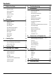
Contents 1. 2. 3. Before You Start... 1 6. Troubleshooting 20 Installation and Maintenance 1 Peculiar Smells 1 Installation 22 If You Smell Gas 1 Ventilation 1 Personal Safety 1 Cooker Care 2 Cleaning 2 Overview 3 7.
iv
1. Before You Start... If You Smell Gas Thank you for buying a Falcon cooker. It should give you many years of trouble-free cooking if installed and operated correctly. It is important that you read this section before you start, particularly if you have not used a dual fuel cooker before. • • • • • • • This appliance is designed for domestic cooking nn only. Using it for any other purpose could invalidate any warranty or liability claim.
When the oven is on, DO NOT leave the oven door nn open for longer than necessary – otherwise, the NEVER leave a chip pan unattended. Always heat fat nn slowly, and watch as it heats. Deep fry pans should Cooking high moisture content foods can create a ‘steam burst’ when the oven door is opened. When opening the oven stand well back and allow any steam to disperse. Foods for frying should be as dry as possible.
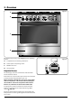
2. Overview Fig. 2.1 A B OFF C D ArtNo.273-0001 - 90 Pro+ FXP annotated The dual fuel single cavity cooker (Fig. 2.1) has the following features: A. 5 hotplate burners including a wok burner B. Control panel incorporating a timer C. Multifunction oven D. Storage drawer ArtNo.270-0001 Proplus control to high Hotplate Burners The drawing by each of the control knobs indicates which burner that knob controls.
Fig. 2.3 If, when you let go of the control knob, the burner goes out, then the FSD has not been bypassed. Turn the control knob to the OFF position and wait for one minute before you try again, this time making sure to hold in the control knob for slightly longer. ArtNo.270-0003 Proplus control to low Adjust the flame height to suit by turning the knob counterclockwise (Fig. 2.3). If a burner flame goes out, turn off the control knob and leave it for one minute before relighting it.
The Griddle Fig. 2.10 The griddle fits the left-hand well, front to back (Fig. 2.11). It is designed for cooking food on directly. DO NOT use pans of any kind on it. The griddle surface is non-stick and metal cooking utensils (e.g. spatulas) will damage the surface. Use heat resistant plastic or wooden utensils. DO NOT put it crossways – it will not fit properly and nn will be unstable. ArtNo.
The Multifunction Oven A Fig. 2.12 The oven is a multifunction oven (Fig. 2.12). In addition to convection elements around the fans, it is fitted with extra heating elements, in the top of the oven and under the oven base. Take care to avoid touching the top elements when placing or removing items from the oven. B The multi-function oven has 3 main cooking functions: fan, fan assisted and conventional cooking. These functions should be used to complete most of your cooking.
door should be kept closed while cooking is in progress, so saving energy. You will also find that the food needs to be watched and turned less than for normal grilling. Preheat this function before cooking. Fig. 2.13 A Note: When grilling full width, to allow sufficient access for tending foods we recommend placing the grill pan tray support on the second from top level. Fan Assisted Oven This function operates the fans, circulating air heated by the elements at the top and the base of the oven.
Self-Cleaning The oven has a self-cleaning function. The oven will run at a high temperature cycle to burn any cooking residue to ash that is easily cleaned away with a damp cloth. For safety, the oven will lock during the cleaning cycle. Fig. 2.14 See the ‘Cleaning’ section for further details on the selfcleaning operation. Energy Saving Panel The oven has a divider feature (Fig. 2.14). With this in place only one half of the oven is heated and only the right-hand side elements are used.
The Clock Fig. 2.18 You can use the 6-button timer (Fig. 2.20) to turn the oven on and off. The clock must be set to the time of day before the oven will work. Fig. 2.19 180 0 22 ArtNo.270-0030 Pro+ FXP oven set to conventional Press and hold both the [C] and [D] buttons as shown in Fig. 2.21. While holding these buttons simultaneously press [–] or [+] until the correct time shows. If you make a mistake or press the wrong button, turn off the power supply for a minute or two and start again. ArtNo.
Fig. 2.28 AUTO is Showing, But You Want to Reset to Manual Cooking Fig. 2.29 ArtNo.302-0005 6BC Stopping the oven 1 When cancelling an automatic setting, any cooking time already set must be returned to ( 0.00 ) before you can return to manual, by pressing the [B] button. ArtNo.302-0005a 6BC Stopping the oven 1a Key Lock Fig. 2.30 When the key lock is activated, the clock can be operated as usual but the oven is locked and will not come on.
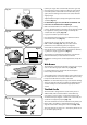
Accessories Fig. 2.35 Each oven is supplied with: • • • • • • Two full capacity shelves (Fig. 2.35) Grill pan tray support (Fig. 2.36) Two grill pans with trivets (Fig. 2.37) Three energy saving shelves (Fig. 2.38) Four ladder shelf supports (Fig. 2.39) And one divider (Fig. 2.40) Fig. 2.36 ArtNo.326-0013 - Full capacity shelf (Falcon) ArtNo.326-0004 - Cradle shelf Fig. 2.37 Fig. 2.38 Oven Shelves Any shelf can be fitted in any of the positions.
Storage Fig. 2.44 The bottom drawer is for storing oven trays and other cooking utensils. It can get very warm, so do not store anything in it that may melt or catch fire. Never store flammable materials in the drawer. This includes paper, plastic and cloth items, such as cookbooks, plastic ware and towels, as well as flammable liquids. Do not store explosives, such as aerosol cans, on or near the appliance. Flammable materials may explode and result in fire nn or property damage.
3. Cooking Tips Cooking with a Multifunction Oven General Oven Tips Remember: not all modes are suitable for all food types. The oven cooking times given are intended for a guide only. The wire shelves should always be pushed firmly to the back of the oven. Tips on Cooking with the Timer Baking trays with food cooking on them should be placed level with the front edge of the oven’s wire shelves. Other containers should be placed centrally.
4. Cooking Table DocNo.031-0004 - Cooking table - electric & fan single cavity The oven control settings and cooking times given in the table below are intended to be used AS A GUIDE ONLY. Individual tastes may require the temperature to be altered to provide a preferred result. Food is cooked at lower temperature in a fan oven than in a conventional oven. When using recipes, reduce the fan oven temperature by 10 °C and the cooking time by 5-10 minutes.
5. Cleaning Your Cooker Isolate the electricity supply before carrying out any major cleaning. Allow the cooker to cool. Fig. 5.1 A NEVER use paint solvents, washing soda, caustic nn cleaners, biological powders, bleach, chlorine based C bleach cleaners, coarse abrasives or salt. DO NOT mix different cleaning products – they may nn react together with hazardous results. B All parts of the cooker can be cleaned with hot soapy water – but take care that no surplus water seeps into the appliance.
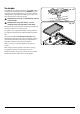
Fig. 5.2 A The Wok Burner ArtNo.311-0014 Wok burner details When reassembling the wok burner (Fig. 5.2) turn over the large base ring and find the ‘D’ shaped area (Fig. 5.3). Turn the head until the ‘D’ matches the one on the burner base. Flip the burner over once again and place it on the burner base. B To fit the small inner burner, find the larger electrode notch in the burner rim. Line this up with the ignition electrode and place the inner burner on the large base ring (Fig. 5.4).
Self-Clean Oven Fig. 5.6 WARNING! Remove all cookware, shelves, and the shelf supports from the oven before using the self-clean function. If the shelves and supports are left in the oven they will discolour and become rough. nn ArtNo.272-0007 FF - MF oven Prof+ pyroOUS Self clean setting WARNING! nn Using the self-cleaning function results in higher temperatures than those for normal cooking. Under such conditions the surfaces may get hotter than usual so children should be kept away.
When the door has unlocked turn the oven function control back to OFF. Fig. 5.10 When the door has unlocked and the oven has cooled, use a damp cloth the clean the debris and ash. To Cancel the Self-Cleaning Cycle To cancel the self-clean function, hold down the [D] button and then press the [–] button to set the timer back to ( 0.00 ). The heating part of the cycle will end and the cooling part of the cycle will start.
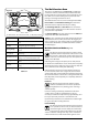
Cleaning Table Cleaners listed are available from supermarkets or electrical retailers as stated (Table 5.2). For enamelled surfaces use a cleaner that is approved for use on vitreous enamel. Regular cleaning is recommended. For easier cleaning, wipe up any spillages immediately. Hotplate Part Finish Recommended Cleaning Method Hob top (including burner heads and caps) Enamel, stainless steel, aluminium Hot soapy water, soft cloth. Any stubborn stains remove gently with a nylon scourer.
6. Troubleshooting Hotplate ignition or cooktop burners faulty Is the power on? If there is an installation problem and I don’t get my original installer to come back to fix it who pays? You do. Service organizations will charge for their call outs if they are correcting work carried out by your original installer. It is in your interest to track down your original installer.
Oven not coming on Is the power on? Fig.6-1 If not there may be something wrong with the power supply. Is the cooker supply on at the circuit breaker? ArtNo.324-0005 Oven light bulb Have you set a cooking function? Oven temperature getting hotter as the cooker gets older If turning the knob down has not worked or only worked for a short time then you may need a new thermostat. This should be fitted by a service person. Fig.6-2 An oven light is not working The bulb has probably burnt out.
INSTALLATION Check the appliance is electrically safe and gas sound when you have finished. 7. Installation Service and Spares Firstly, please complete the appliance details below and keep them safe for future reference – this information will enable us to accurately identify the particular appliance and help us to help you. Filling this in now will save time and inconvenience if you later have a problem with the appliance. It may also be of benefit to keep your purchase receipt with this leaflet.
INSTALLATION Check the appliance is electrically safe and gas sound when you have finished. Provision of Ventilation You must be aware of the following safety requirements & regulations. This appliance is not connected to a combustion products evacuation device. Particular attention shall be given to the relevant requirements regarding ventilation.
INSTALLATION Check the appliance is electrically safe and gas sound when you have finished. You will need the following equipment to complete the cooker installation satisfactorily: • Flexible gas hose. • Gas pressure tester/manometer. • Multimeter: For electrical checks. Checking the Parts: Pan supports ArtNo.000-0001 90 Pan supports You will also need the following tools: 1. Electric drill 2. Masonry drill bit (only required if fitting the cooker on a stone or concrete floor) 3.
INSTALLATION Check the appliance is electrically safe and gas sound when you have finished. Positioning the Cooker Fig.7-1 The diagram (Fig.7-1) shows the minimum recommended distance from the cooker to nearby surfaces as given in AS 5601. A *Any splashback must be fitted in accordance with the manufacturers instructions. Allowance should be made for the additional height of the flue trim, which is fitted to the cooker hob. 1. * ArtNo.
INSTALLATION Check the appliance is electrically safe and gas sound when you have finished. Moving the Cooker Fig.7-2 On no account try and move the cooker while it is nn plugged into the electricity supply. The cooker is very heavy, so take great care. nn We recommend that two people manoeuvre the cooker. Make sure that the floor covering is firmly fixed, or removed, to prevent it being disturbed when moving the cooker around.
INSTALLATION Check the appliance is electrically safe and gas sound when you have finished. Levelling Fig.7-6 You are recommended to use a spirit level on a shelf in one of the ovens to check for level. Place the cooker in its intended position, taking care not to twist it within the gap between the kitchen units as damage may occur to the cooker or the units. The front feet and rear rollers can be adjusted to level the cooker.
INSTALLATION Check the appliance is electrically safe and gas sound when you have finished. Gas Connection Fig.7-10 40 Must be in accordance with the relevant standards. The gas supply needs to terminate with a threaded fitting ½”. The inlet connector is located just below the hotplate level at the rear of the cooker. 80 140 330 Because the height of the cooker can be adjusted and each connection is different it is difficult to give precise dimensions.
INSTALLATION Check the appliance is electrically safe and gas sound when you have finished. Electrical Connection Fig.7-11 This appliance must be installed by a qualified electrician to comply with the relevant regulations (AS/NZS 60335.2.6) and also the local electricity supply company requirements. Make sure that the mains characteristics (voltage, nominal, power, etc.) match the ratings indicated on the cooker data plate. ArtNo.
INSTALLATION Check the appliance is electrically safe and gas sound when you have finished. Final Checks Fig.7-15 Hotplate Check Check each burner in turn. There is a Flame Supervision Device (FSD) that stops the flow of gas to the burner if the flame goes out. For each burner, turn the control knob to the solid flame symbol. Press in the control knob. This lets gas through to the burner. Keep holding the knob pressed in and press the igniter button or light with a match.
WARNING – SERVICING TO BE CARRIED OUT ONLY BY AN AUTHORISED PERSON Disconnect from electricity and gas before servicing. Check appliance is safe when you have finished. 8. Conversion to Propane Gas Conversion from Natural Gas (1.0 kPa) to LPG X Propane (2.54 kPa) Fig.8-1 A suitably competent person must perform the nn conversion. After conversion the installation must comply with the relevant regulations and also the local electricity supply company requirements.
WARNING – SERVICING TO BE CARRIED OUT ONLY BY AN AUTHORISED PERSON Disconnect from electricity and gas before servicing. Check appliance is safe when you have finished. Set the Governor Fig.8-5 Unscrew the governor’s brass top. In the base of the brass top is a plastic snap-in converter device (Fig.8-5). To convert the governor, snap the device out of the top and refit it the other way round. The snap-in converter device is marked to show the gas for which it is set (Fig.8-6). ArtNo.
WARNING – SERVICING TO BE CARRIED OUT ONLY BY AN AUTHORISED PERSON Disconnect from electricity and gas before servicing. Check appliance is safe when you have finished. 9. Servicing BEFORE SERVICING ANY GAS CARRYING nn COMPONENTS TURN OFF THE GAS SUPPLY Fig.9-1 Check the appliance is gas sound after completion nn of service. When checking for gas leaks DO NOT use washing up liquid – this can corrode. Use a product specifically manufactured for leak detection.
WARNING – SERVICING TO BE CARRIED OUT ONLY BY AN AUTHORISED PERSON Disconnect from electricity and gas before servicing. Check appliance is safe when you have finished. 2 Wok Burner Disconnect the burner feed pipes at the burner. Fit the new one and reassemble in reverse order. Check that the burner operation is satisfactory. Hotplate 2.1 To Remove the Hotplate DISCONNECT FROM THE ELECTRICITY SUPPLY. Remove the pan supports and burner heads.
WARNING – SERVICING TO BE CARRIED OUT ONLY BY AN AUTHORISED PERSON Disconnect from electricity and gas before servicing. Check appliance is safe when you have finished. 4 Ovens Fig.9-5 4.1 To Change an Oven Thermostat Protection & primary phials DISCONNECT FROM THE ELECTRICITY SUPPLY. Situated at the back of the oven, behind the righthand upper elements, are the primary and protection thermostats phials. One the right-hand side of the same element is the pyrolytic phial (Fig.9-5).
WARNING – SERVICING TO BE CARRIED OUT ONLY BY AN AUTHORISED PERSON Disconnect from electricity and gas before servicing. Check appliance is safe when you have finished. 4.3 To Replace the Oven Catalytic Converter Fig.9-7 DISCONNECT FROM THE ELECTRICITY SUPPLY. Undo the 2 screws holding the catalytic filter cover in place (Fig.9-7) and remove. Pull out the catalytic assembly. Replace the catalyst and fit in reverse, making sure that the cover fits over the ends of the thermostat phials.
WARNING – SERVICING TO BE CARRIED OUT ONLY BY AN AUTHORISED PERSON Disconnect from electricity and gas before servicing. Check appliance is safe when you have finished. Top Element Remove the top element bracket fixings and withdraw the elements carefully, lifting to clear the clips on the support bar (Fig.9-12). Replace the element and reassemble the parts in reverse order. Check that the oven operates satisfactorily. Fig.9-12 ArtNo281-0147 Top Element Fixings 4.8 To Replace the Cooling Fan Fig.
WARNING – SERVICING TO BE CARRIED OUT ONLY BY AN AUTHORISED PERSON Disconnect from electricity and gas before servicing. Check appliance is safe when you have finished. 5 Fig.9-16 Door 5.1. To Remove the Oven Door CAUTION! The door is very heavy. Take care when removing. To remove the door, open the door fully. Swivel the locking ‘U’ clips forward to the locking position (Fig.9-16). Grip the sides of the door, lift upwards and then slide the door forwards (Fig.9-17) and remove. ArtNo.
WARNING – SERVICING TO BE CARRIED OUT ONLY BY AN AUTHORISED PERSON Disconnect from electricity and gas before servicing. Check appliance is safe when you have finished. 5.5. To Replace the Oven Door Hinge Centre glass panel assembly Remove the oven door (see 5.1). Lift out the inner panel and place it, outer side up, on a clean level surface. Undo the screws securing the hinge in place. Remove the hinge. Replace the hinge and rebuild the door in reverse order. Fig.9-20 Gasket 5.
10.
11. Technical Data This cooker is designed for use on Natural gas, although a conversion for LP (LPG X Propane (2.54 kPa)) gas is packed with the cooker. INSTALLER: Please leave these instructions with the user. DATA BADGE LOCATION: Inside base drawer of cavity and on rear of the appliance. COUNTRY OF DESTINATION: Australia. Connection & Test Pressures Gas (Rp½ at right rear) Natural Gas Electric 1 kPa Propane 230 V 50 Hz 2.54 kPa See appliance data badge for test pressures.
42
43
Clarence Street, Royal Leamington Spa, Warwickshire, CV31 2AD, England. Tel: +44 (0) 1926 457400 Fax: +44 (0) 1926 450526 E-mail: consumers@falconappliances.co.