
Installation and Operation Guide


WARNING – SERVICING TO BE CARRIED OUT ONLY BY AN AUTHORISED PERSON
Disconnect from electricity and gas before servicing. Check appliance is safe when you have nished.
37
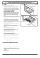
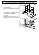
Top Element
Remove the top element bracket xings and withdraw
the elements carefully, lifting to clear the clips on the
support bar (Fig.9-12).
Replace the element and reassemble the parts in
reverse order.
Check that the oven operates satisfactorily.
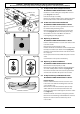
4.8 To Replace the Cooling Fan
Remove the hotplate (see 2.1).
Remove the access plate.
Remove the screws that hold the cooling fan to the duct
(Fig.9-13), and then lift out the fan.
Reassemble in reverse order.
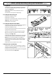
4.9 To Replace the Oven Latch Motor
Remove the packing and accessories from the appliance
except the base pack that can be left in place.
Remove the hotplate (see 2.1).
Disconnect the thermal cut-out. Disconnect the motor
leads from the terminal block.
Undo the 3 cover plate screws and remove the plate.
Open the oven door and undo the 2 latch assembly
retaining screws (Fig.9-14).
Remove the black, orange and purple wires connected
to the latch motor. Remove the latch motor assembly.
Note: The access to the assembly is very tight; it is
suggested that the assembly is slid into the cooker so
that the latch can be turned sideways and then lifted
out front rst.
Replace the motor and ret in reverse order.
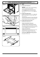
4.10 To Override a Locked Oven
Switch on the cooker. Set the oven function control to
self-clean – do not set the timer. This should switch the
lock back to the open position.
If this fails, then get a wire hook and slide in through the
side to pull the latch back (Fig.9-15).
Fig.9-13
Fig.9-14
Fig.9-15
ArtNo281-0147 Top Element Fixings
Fig.9-12