ArtNo.
Contents 1. 2. 3. Before You Start... 1 6. Troubleshooting 20 Installation and Maintenance 1 Peculiar Smells 1 7.
1. Before You Start... This User Guide covers a number of different models. Although some of the illustrations will look different to your particular model the functions will be the same. We hope the meaning is clear. Ventilation CAUTION: The use of a gas cooking appliance results nn in the production of heat and moisture in the room in which it is installed. Make sure that the kitchen is well ventilated: keep natural ventilation holes open or install a powered cookerhood that vents outside.
DO NOT use water on grease fires and never pick nn up a flaming pan. Turn the controls off and then Cooking high moisture content foods can create a ‘steam burst’ when an oven door is opened. When opening the oven stand well back and allow any steam to disperse. smother a flaming pan on a surface unit by covering the pan completely with a well fitting lid or baking tray. If available, use a multi-purpose dry chemical or foam-type fire extinguisher. ArtNo.
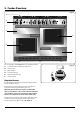
2. Cooker Overview DocNo.020-0021 - Overview - 110DF - Kitchener-Prof+ Fig.2-1 A Professional + B C E D F The 110 dual fuel cooker (Fig.2-1) has the following features: A. B. C. D. E. F. ArtNo.270-0001 Proplus control to high 6 hotplate burners including a wok burner Control panel Glide-out grill Conventional oven Programmable fan oven Storage drawer Hotplate Burners The drawing by each of the central knobs indicates which burner that knob controls.
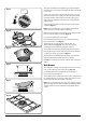
Fig.2-3 The igniter should spark and light the gas. Keep holding the knob pressed in to let the gas through to the burner for about ten seconds. ArtNo.270-0003 Proplus control to low If, when you let go of the control knob, the burner goes out, then the FSD has not been bypassed. Turn the control knob to the OFF position and wait for one minute before you try again, this time making sure to hold in the control knob for slightly longer.
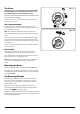
The Wok Cradle (optional) Fig.2-9 The wok cradle is designed to fit a 35 cm wok. If you use a different wok, make sure that it fits the cradle. Woks vary very widely in size and shape. It is important that the wok sits down on the pan support – however, if the wok is too small, the cradle will not support it properly (Fig.2-9). The cradle should be used on the triple ring wok burner only.
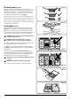
The Grill / Glide-out Grill Fig.2-15 CAUTION: This appliance is for cooking purposes nn only. It must not be used for other purposes, for example room heating. CAUTION: Accessible parts may be hot when the grill nn is in use. Young children should be kept away. ArtNo.330-0003 - Grill pan w handle pulled forwards Open the door and pull the grill pan (Fig.2-15) or carriage (Fig.2-16) forward using the handle.
The Ovens Fig.2-19 The clock must be set to the time of day before the righthand oven will work. See the following section on ‘The Clock’ for instructions on setting the time of day. References to ‘left-hand’ and ‘right-hand’ ovens apply as viewed from the front of the appliance. ArtNo.235-0004 Classic DL oven 1 The left-hand oven is a conventional oven, while the righthand oven is a fan oven.
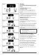
Fig.2-21 The Clock ArtNo.300-0004 2-button clock annotated You can use the clock to turn the right-hand oven on and off. The clock must be set to the time of day before the oven will work. The 2-button Clock (Professional+) Setting the Time of Day A The 2-button LCD clock is shown in (Fig.2-21). When the clock is first connected, the display flashes ( 0.00 ) and ( ) alternately. B A – Timer knob, B – Adjusting knob Fig.
Turn the Timer knob to the [] position. The display will show the current time of day plus the ‘cook period’ you just set. Use the Adjusting knob to set the ‘stop time’ required (Fig.2-28). ArtNo.301-0008 2BC Stopping the oven 2 Fig.2-28 Art No. 301-0011 2BC Activating the key lock 1 Fig.2-29 ArtNo.301-0012 2BC Activating the key lock 2 Fig.2-30 ArtNo.301-0013 2BC Activating the key lock 3 Fig.2-31 ArtNo.301-0014 2BC Deactivating the key lock 1 Fig.2-32 ArtNo.
The 6-button Clock (Kitchener) Fig.2-34 Setting the Time of Day The 6-button LCD clock is shown in Fig.2-34. When the clock is first connected the display flashes ( 0.00 ) and ( alternately. ) ArtNo.302-0002 - 6BC annotated A B C D E Press and hold both the [] and [] buttons down (Fig.2-35). now press the [+] button (or the [–] button) until the correct time shows. F Do not forget that it is a 24-hour clock.
AUTO is Showing, But You Want to Reset to Manual Cooking Fig.2-44 To return to manual cooking from any automatic setting, the ‘cook period’ must be cancelled. Press and hold the [] button and then press the [–] button until the display reads ( 0.00 ). Fig.2-45 ArtNo.302-0008 Activating the key lock 1 Press the [] button to return to manual cooking. ArtNo.302-0009 - Activating the key lock 2 Key Lock Activating the key lock will lock the programmable oven and it will not come on. Fig.
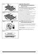
Accessories Fig.2-49 Flat shelf Oven Shelves Shelf guard In addition to the flat shelves, the cooker is supplied with a drop shelf (Fig.2-49). The drop shelf increases the possibilities for oven shelf spacing. Front The oven shelves can be easily removed and refitted. Pull the shelf forward until the back of the shelf is stopped by the shelf stop bumps in the oven sides (Fig.2-50).
Main Oven Lights Fig.2-56 Press the button to turn the lights on (Fig.2-56). If an oven light fails, turn off the power supply before changing the bulb. See the ‘Troubleshooting’ section for details on how to change the bulb. ArtNo.320-0017 Main oven light Storage The bottom drawer is for storing oven trays and other cooking utensils. It can get very warm, so do not store anything in it that may melt or catch fire. Fig.2-57 The drawer can be removed completely by pulling it right out and up (Fig.
3. Cooking Tips Tips on Cooking with the Timer General Oven Tips If you want to cook more than one dish, choose dishes that require approximately the same cooking time. However, dishes can be ‘slowed down’ slightly by using small containers and covering them with aluminium foil, or ‘speeded up’ slightly by cooking smaller quantities or placing them in larger containers. The wire shelves should always be pushed firmly to the back of the oven.
4. Cooking Table DocNo.031-0004 - Cooking table - electric & fan single cavity The oven control settings and cooking times given in the table below are intended to be used AS A GUIDE ONLY. Individual tastes may require the temperature to be altered to provide a preferred result. Food is cooked at lower temperature in a fan oven than in a conventional oven. When using recipes, reduce the fan oven temperature by 10 °C and the cooking time by 5-10 minutes.
5. Cleaning Your Cooker DocNo.040-0007 - Cleaning - 110DF GENERIC Essential Information Fig.5-1 A Isolate the electricity supply before carrying out any thorough cleaning. Allow the cooker to cool. C NEVER use paint solvents, washing soda, caustic nn cleaners, biological powders, bleach, chlorine based B bleach cleaners, coarse abrasives or salt. DO NOT mix different cleaning products – they may nn react together with hazardous results.
Grills Fig.5-5 The grill pan and trivet should be washed in hot soapy water. Alternatively, the grill pan can be washed in a dishwasher. After grilling meats or any foods that soil, leave to soak for a few minutes immediately after use. Stubborn particles may be removed from the trivet using a nylon brush. Before you remove any of the grill parts for cleaning, nn make sure that they are cool, or use oven gloves. ArtNo.
Control Panel and Doors Fig.5-10 Avoid using any abrasive cleaners, including cream cleaners. For best results, use a liquid detergent. The same cleaner can also be used on the doors, or alternatively, using a soft cloth wrung out in clean hot soapy water. You can use the same method for cleaning the control panel and knobs. After cleaning, polish with a dry cloth. Glass Fronted Door Panel ArtNo.
Cleaning Table Cleaners listed (Table 5-1) are available from supermarkets or electrical retailers as stated. For enamelled surfaces use a cleaner that is approved for use on vitreous enamel. Regular cleaning is recommended. For easier cleaning, wipe up any spillages immediately. Hotplate Part Finish Recommended Cleaning Method Hob top Enamel or stainless steel Hot soapy water, soft cloth. Any stubborn stains remove gently with a nylon scourer.
6. Troubleshooting Hotplate ignition or hotplate burners faulty Is the power on? Is the clock illuminated? Power failure In the event of a failure in the electrical supply, remember to reset the clock to make sure that the timed oven continues to operate. If not, there maybe something wrong with the power supply. Food is cooking too slowly, too quickly, or burning Cooking times may differ from your previous oven.
An oven light is not working The bulb has probably burnt out. You can buy a replacement bulb (which is not covered under the warranty) from a good electrical shop. Ask for a 15 W – 230 V lamp, FOR OVENS. It must be a special bulb, heat resistant to 300 °C (Fig.6-1). Fig.6-1 ArtNo.324-0005 Oven light bulb Turn off the power at the circuit breaker. Before removing the existing bulb, turn off the power supply and make sure that the oven is cool. Open the oven door and remove the oven shelves. Fig.
INSTALLATION Check the appliance is electrically safe and gas sound when you have finished. 7. Installation Service and Spares Firstly, please complete the appliance details below and keep them safe for future reference – this information will enable us to accurately identify the particular appliance and help us to help you. Filling this in now will save time and inconvenience if you later have a problem with the appliance. It may also be of benefit to keep your purchase receipt with this leaflet.
INSTALLATION Check the appliance is electrically safe and gas sound when you have finished. Dear Installer Provision of Ventilation Before you start your installation, please complete the details below, so that, if your customer has a problem relating to your installation, they will be able to contact you easily. This appliance is not connected to a combustion products evacuation device. Particular attention shall be given to the relevant requirements regarding ventilation.
INSTALLATION Check the appliance is electrically safe and gas sound when you have finished. You will need the following equipment to complete the cooker installation satisfactorily: • • • Checking the Parts: 4 pan supports Flexible gas hose. Gas pressure tester/manometer. Multimeter: For electrical checks. ArtNo.000-0009 Wok ring, cast You will also need the following tools: 1. Electric drill 2. Masonry drill bit (only required if fitting the cooker on a stone or concrete floor) 3.
INSTALLATION Check the appliance is electrically safe and gas sound when you have finished. Positioning the Cooker Fig.7-1 The diagram (Fig.7-1) shows the minimum recommended distance from the cooker to nearby surfaces as given in AS 5601. 1. Overhead – Measurement A A The minimum height of any surface above the cooker is 650 mm above the hotplate. B D C E Cookerhoods and exhaust fans shall be installed in accordance with the manufacturer’s instructions.
INSTALLATION Check the appliance is electrically safe and gas sound when you have finished. Moving the Cooker Fig.7-3 On no account try and move the cooker while it is nn plugged into the electricity supply. The cooker is very heavy, so take great care. nn We recommend that two people manoeuvre the cooker. Make sure that the floor covering is firmly fixed, or removed, to prevent it being disturbed when moving the cooker around.
INSTALLATION Check the appliance is electrically safe and gas sound when you have finished. Fitting the Stability Bracket and Chain Fig.7-6 Stability bracket A stability bracket and chain MUST be fitted when the cooker is connected to a flexible gas supply. nn Unless properly installed, the cooker could be tipped by leaning on the door. Injury might result from spilled hot liquids or from the cooker itself.
INSTALLATION Check the appliance is electrically safe and gas sound when you have finished. Fig.7-9 Gas Connection 600 Must be in accordance with the relevant standards. 350 The gas supply needs to terminate with a down-facing threaded fitting ½” connection. The inlet connector is located just below the hotplate level at the rear of the cooker. 100 250 Because the height of the cooker can be adjusted and each connection is different it is difficult to give precise dimensions.
INSTALLATION Check the appliance is electrically safe and gas sound when you have finished. Electrical Connection Fig.7-10 This appliance must be installed by a qualified electrician to comply with the relevant regulations (AS/NZS 60335.2.6) and also the local electricity supply company requirements. Make sure that the mains characteristics (voltage, nominal, power, etc.) match the ratings indicated on the cooker data plate. ArtNo.
INSTALLATION Check the appliance is electrically safe and gas sound when you have finished. Replace the electric terminal cover box; make sure that the conduit is clear of the bottom flange. Fig.7-14 Checks Note: The clock must be set before the ovens will work. See ‘The Clock’ section for instructions on setting the time of day. Hotplate Check ArtNo.281-0026 - Front plinth Check each burner in turn.
WARNING – SERVICING TO BE CARRIED OUT ONLY BY AN AUTHORISED PERSON Disconnect from electricity and gas before servicing. Check appliance is safe when you have finished. 8. Conversion to Propane Gas DocNo.080-0003 - Gas conversion - 110RM - Tag-fit fascia Conversion from Natural Gas (1.0 kPa) to LPG X Propane (2.54 kPa) Fig.8-1 This conversion must be performed by a competent nn person, in accordance with these instructions and with the local supply company requirements.
WARNING – SERVICING TO BE CARRIED OUT ONLY BY AN AUTHORISED PERSON Disconnect from electricity and gas before servicing. Check appliance is safe when you have finished. Set the Governor Fig.8-4 Unscrew the governor’s brass top. In the base of the brass top is a plastic snap-in converter device (Fig.8-4). To convert the governor, snap the device out of the top and refit it the other way round. The snap-in converter device is marked to show the gas for which it is set (Fig.8-5). ArtNo.
WARNING – SERVICING TO BE CARRIED OUT ONLY BY AN AUTHORISED PERSON Disconnect from electricity before servicing. Check appliance is safe when you have finished. 9. Servicing BEFORE SERVICING ANY GAS CARRYING nn COMPONENTS TURN OFF THE GAS SUPPLY. Fig.9-1 Check the appliance is gas sound after completion nn of service. When checking for gas leaks do not use washing up liquid – this can corrode. Use a product specifically manufactured for leak detection.
WARNING – SERVICING TO BE CARRIED OUT ONLY BY AN AUTHORISED PERSON Disconnect from electricity before servicing. Check appliance is safe when you have finished. IMPORTANT: Make sure you replace the rear earthing leads when refitting the fixing screws as they form part of the cooker earthing. Check for correct burner operation. 3 Control Panel 3.1 To Replace the Ignition or Light Switch DISCONNECT FROM THE ELECTRICITY SUPPLY. Remove the control panel (see 1.1).
WARNING – SERVICING TO BE CARRIED OUT ONLY BY AN AUTHORISED PERSON Disconnect from electricity before servicing. Check appliance is safe when you have finished. the screws securing the electric cover to the back sheet, and then remove cover and disconnect the terminals from the rear. Fit the new elements and reassemble in reverse order. Check the operation of the grill. 5 Fig.9-3 Ovens 5.1 To Replace an Oven Thermostat DISCONNECT FROM THE ELECTRICITY SUPPLY. Remove the control panel and hotplate (see 1.
WARNING – SERVICING TO BE CARRIED OUT ONLY BY AN AUTHORISED PERSON Disconnect from electricity before servicing. Check appliance is safe when you have finished. Fit the replacement control and re-assemble in the reverse order. Fig.9-4 5.5 To Remove the Right-hand Oven Element DISCONNECT FROM THE ELECTRICITY SUPPLY. Remove oven inner back (see 5.2). Remove the 2 screws from the top of the element and the 1 from the bottom of the element (Fig.9-4).
WARNING – SERVICING TO BE CARRIED OUT ONLY BY AN AUTHORISED PERSON Disconnect from electricity before servicing. Check appliance is safe when you have finished. 6.2 To Replace an Oven Door Fig.9-9 Centreline of hinge pin Open the oven door. Support the door and loosen the 2 screws securing the upper hinge and gasket to the cooker front (Fig.9-7). The door is heavy, so take care. nn Support the door and remove the screw nearest the hinge pin (Fig.9-8).
10.
11. Technical Data DocAUS.102-0004 - Technical data - 110DF - Prof+ This cooker is designed for use on Natural Gas, although a conversion for LP (LPG X Propane (2.54 kPa)) gas is packed with the cooker. INSTALLER: Please leave these instructions with the user. DATA BADGE LOCATION: Cooker back. The serial number is repeated on the badge below the left-hand oven door opening. COUNTRY OF DESTINATION: Australia.
Notes 40
Notes 41
Clarence Street, Royal Leamington Spa, Warwickshire, CV31 2AD, England. Tel: +44 (0) 1926 457400 Fax: +44 (0) 1926 450526 E-mail: consumers@falconappliances.co.