
User's Manual
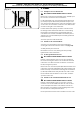
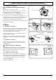
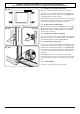
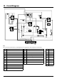
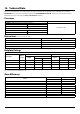
Table Of Contents
- U111290 cover - Falcon
- U111290-01 [AUS]
- 1. Before You Start...
- 2. Cooker Overview
- 3. Rotary clock
- 4. 3 button clock
- 5. Cooking Tips
- 6. Cooking Table
- 7. Cleaning your cooker
- 8. Troubleshooting
- 9. Service and Spares
- 10. Installation
- Provision of Ventilation
- Location of Cooker
- Conversion
- Positioning the Cooker
- Moving the Cooker
- Lowering the Two Rear Rollers
- Completing the Move
- Levelling
- Fitting the Stability Bracket and Chain
- Fitting the Stability Bracket
- Fitting the Restraining Chain
- Gas Connection
- Pressure Testing
- Electrical Connection
- Connection in New Zealand
- Fixed Wiring
- Final Checks
- Final Fitting
- Customer Care
- 11. Conversion to LP Gas
- 12. Servicing
- 13. Circuit Diagram
- 14. Technical Data

44
13. Circuit Diagram
P095199
2
P2
P1
1
P095199
2
P2
P1
1
a
b
e
f
c
d
1
2
b
v
P095199
2P2
P1
1
br bbbb
r
b
b
r
y
b
b
br
v
bk
bk
v
v
br
y
b
y
br
y
y
br
b
br
b
br
b
bk
b
g/y
v
y
y
or
or
g/y
r
r
bk
br
br
or
y
b
bk
bk
v
br
b
r
b
b
v
b
b
r
r
r
v
y
y
y
b
r
b
r
b
b
bbr br
br
b
b
y
br br b
br
v
or
y
E
A2
C
A1
AN
H
G1
B3
B4
B2
B1
D3
J
G2
H
F1
D1
J
D2
D4
K
J
A3
F2
F3
Code Description
A1
Grill front switch
A2
Grill energy control
A3
Grill elements
B1
Left hand oven front switch
B2
Left hand oven front thermostat
B3
Left hand oven fan
B4
Left hand oven fan element
C
Clock
D1
Right hand oven front switch
D2
Right hand oven thermostat
D3
Right hand oven fan
D4
Right hand oven fan element
Key
The connections shown in the circuit diagram are for single-phase. The ratings are for 230 V 50 Hz.
Code Colour
b
Blue
br
Brown
bk
Black
or
Orange
r
Red
v
Violet
w
White
y
Yellow
g/y
Green/yellow
Code Description
F1
Oven light switch
F2
Ignition switch
F3
Ignition spark generator
G1
Left hand oven light
G2
Right hand oven light
H
Thermal
J
Neon
K
Cooling fan