USER GUIDE & INSTALLATION INSTRUCTIONS Classic / Professional+ 110 Dual Fuel Australia U111290-01
Contents 1. 2. 1 9. Personal Safety 1 Electrical Connection Safety 2 10. Installation If You Smell Gas 2 Peculiar Smells 2 Cooling Fan 2 Ventilation 3 Maintenance 3 Grill/Glide-out Grill™ Care 5 Cooker Care 5 Cleaning 5 Before You Start...
1. Before You Start... Your cooker should give you many years of trouble-free cooking if installed and operated correctly. It is important that you read this section before you start. • DO NOT operate with panels, covers or guards removed from this appliance. • The cooker should not be placed on a base. This User Guide covers a number of different models. Although some of the illustrations will look different to your particular model the functions will be the same. We hope the meaning is clear.
• DO NOT use a steam cleaner on your cooker. • Always keep combustible materials, e.g. curtains, and flammable liquids a safe distance away from the cooker. • DO NOT spray aerosols in the vicinity of the cooker while it is on. • Make sure that the gas supply is turned on and that the cooker is wired in and switched on. • In your own interest and that of safety, it is law that all gas appliances be installed by a qualified person(s).
Ventilation • The use of a cooking appliance results in the production of heat and moisture in the room in which it is installed. Therefore, make sure that the kitchen is well ventilated: keep natural ventilation holes open or install a powered cookerhood that vents outside. If you have several hotplates/burners on, or use the cooker for a long time, open a window or turn on an extractor fan WARNING: Unattended cooking on a n hob with fat or oil can be dangerous and may result in fire.
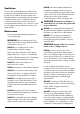
Fig. 1.1 ArtNo.324-0001 Steam burst • DO NOT modify this appliance. This appliance is not intended to be operated by means of external timer or separated remote-control system. • If flammable materials are stored in the drawer, oven(s) or grill(s) it may explode and result in fire or property damage. Oven Care Fig. 1.2 Front bracket • When the oven is not in use and before attempting to clean the cooker always be certain that the control knobs are in the OFF position.
• DO NOT use the timed oven if the adjoining oven is already warm. • DO NOT place warm food in the oven to be timed. • DO NOT use a timed oven that is already warm. • Use dry oven gloves when applicable – using damp gloves might result in steam burns when you touch a hot surface. Cooker Care As steam can condense to water droplets on the cool outer trim of the oven, it may be necessary during cooking to wipe away any moisture with a soft cloth.
6 • DO NOT put the burner heads in a dishwasher. • NEVER use caustic or abrasive cleaners as these will damage the surface. • DO NOT use steel wool, oven cleaning pads or any other materials that will scratch the surface. • NEVER store flammable materials in the drawer. This includes paper, plastic and cloth items, such as cookbooks, plastic ware and towels, as well as flammable liquids. • DO NOT store explosives, such as aerosol cans, on or near the appliance.
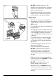
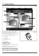
2. Cooker Overview DocNo.020-0013 - Overview - 110DF - Classic, RM & Toledo lidded Fig. 2.1 A B C E M D F This User Guide covers a number of different models. Although some of the illustrations will look different to your particular model the functions will be the same. Fig. 2.2 The 110 dual fuel cooker (Fig. 2.1) has the following features: A. 6 hotplate burners including a wok burner B. A control panel C. A glide-out grill D. A (programmable) fan oven E. A Fan oven F.
To light a burner, press the igniter button, and push in and turn the associated control knob to the high position as indicated by the large flame symbol (), (Fig. 2.2). Fig. 2.3 The igniter should spark and light the gas. Keep holding the knob pressed in to let the gas through to the burner for about ten seconds. If, when you let go of the control knob, the burner goes out, then the FSD has not been bypassed.
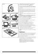
The Wok Cradle* (Optional) Fig. 2.9 The wok cradle is designed to fit a 35 cm wok. If you use a different wok, make sure that it fits the cradle. Woks vary very widely in size and shape. It is important that the wok sits down on the pan support – however, if the wok is too small, the cradle will not support it properly (Fig. 2.9). The cradle should be used on the wok burner only.
The Grill Fig. 2.15 n CAUTION: This appliance is for cooking purposes only. It must not be used for other purposes, for example room heating. n CAUTION: Accessible parts may be hot when the grill is in use. Young children should be kept away. Open the door and pull the grill pan forward using the handle (Fig. 2.15). ArtNo.331-0001Grill pan pulled forwards The grill has two elements that allow either the whole area of the pan to be heated or just the right-hand half. Fig. 2.
The Ovens Fig. 2.18 The clock must be set to the time of day before the ovens will work. See the following section on ‘The Clock’ for instructions on setting the time of day. Fan oven References to ‘left-hand’ and ‘right-hand’ ovens apply as viewed from the front of the appliance. The left-hand oven is a programmable fan oven (Fig. 2.18), while the right-hand oven is a fan oven (Fig. 2.19). nevo detsissa naF 2000-123.
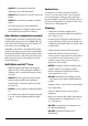
Accessories Fig. 2.23 Shelf guard Oven Shelves The oven shelves (Fig. 2.23) can be easily removed and refitted. Pull the shelf forward until the back of the shelf is stopped by the shelf stop bumps in the oven sides (Fig. 2.24). Front Lift up the front of the shelf so the back of the shelf will pass under the shelf stop and then pull the shelf forward (Fig. 2.25). Fig. 2.24 Fig. 2.25 ArtNo.
Glide-out Oven Shelf (optional) Fig. 2.30 A glide-out oven shelf is available for either oven (Fig. 2.30). Note: The Handyrack must be removed before fitting the glide-out shelf. The rungs on the shelf supports are in pairs. The glide-out shelf runners can be fitted to any pair except the top. To fit the glide-out shelf runners FRONT Hook the rear of the runner over the top rung of a pair of shelf supports. Then hook the front of the runner onto the same rung. Push to clip under the bottom rung (Fig. 2.
3. Rotary clock To stop the oven at a specific time of day Symbol key (main oven only) You have set the required temperature and function mode and you would like the oven to automatically stop. manual clock Step. 1 minute minder Note: The cook symbol [ ] remains visible during normal operation. cook time stop time auto 1 1 Setting the time Step. 2 Set the time of day you want the oven to stop cooking, for example add 1 hour.
To start and stop the oven automatically (main oven only) The timer allows you to automatically start and stop by a combination of the length of the cooking time and the stop time. Giving you the flexibility to cook casseroles etc while you are out. You cannot set the actual start time. Step. 1 Set the cook time Step. 4. Alarm will sound when cooking has finished, to cancel follow this step 1 1 1 2 B 1 Step. 2 n REMEMBER Turn the oven control knob(s) to 0.
4. 3 button clock Setting the time The clock must be set to the time of day before the oven will work Reset the minute minder Step. 1 Note: The cook symbol [ ] remains visible during normal operation. Step. 1 ArtNo.306-0001 - 3-button clock ArtNo.306-0001 - 3-button clock Step. 2 Step. 2 Press the [+] and [-] buttons simultaneously. Press either [+] or [-] buttons. ArtNo.306-0001 - 3-button clock ArtNo.
To start and stop the oven automatically (main oven only) Step. 1 AUTO is showing, but you want to revert to manual cooking (main oven only) Press [M] button again until current time is diplayed. Press either [+] or [-] buttons ArtNo.306-0001 - 3-button clock Step. 2 ArtNo.306-0001 - 3-button clock Set the length of time you want the oven to cook for. ArtNo.306-0001 - 3-button clock Changing the frequency of the alarm Step. 1 Press [M] button again until current time is diplayed.
5. Cooking Tips Tips on cooking with the timer General oven tips If you want to cook more than one dish, choose dishes that require approximately the same cooking time. However, dishes can be ‘slowed down’ slightly by using small containers and covering them with aluminium foil, or ‘speeded up’ slightly by cooking smaller quantities or placing them in larger containers. The wire shelves should always be pushed firmly to the back of the oven.
6. Cooking Table The oven control settings and cooking times given in the table below are intended to be used as a guide only. Individual tastes may require the temperature to be altered to provide a preferred result. Food is cooked at lower temperature in a fan oven than in a conventional oven. When using recipes, reduce the fan oven temperature by 10 °C and the cooking time by 5-10 minutes. The temperature in the fan oven does not vary with height in the oven so you can use any shelf.
7. Cleaning your cooker Essential Information Fig. 7.1 Isolate the electricity supply before carrying out any thorough cleaning. Allow the cooker to cool. n n A C NEVER use paint solvents, washing soda, caustic cleaners, biological powders, bleach, chlorine based bleach cleaners, coarse abrasives or salt. B DO NOT mix different cleaning products – they may react together with hazardous results.
Fig. 7.5 The Griddle ArtNo.331-0003 Grill frame out, no pan Always clean the griddle after use. Allow it to cool completely before removing. Immerse the griddle plate in hot soapy water. Use a soft cloth or, for stubborn stains, a nylon washing up brush. NOTE: If the griddle is washed in a dishwasher then some dishwasher residue may appear on the back. This is normal and will not affect the performance of your griddle. Glide-out Grill Fig. 7.6 n Before you remove any of the grill parts for cleaning.
Glass Fronted Door Panels Fig. 7.8 The oven door front panels can be taken off so that the glass panels can be cleaned. Move the cooker forward to gain access to the sides (see the ‘Moving the Cooker’ section under ‘Installation’). Open the oven door slightly and remove the front panel fixing screws from the door sides, two each side (Fig. 7.8). Carefully lift off the outer door panel. The inside face of the glass panels can now be cleaned – take care not to disturb or wet the door insulation. ArtNo.
Cleaning table Cleaners listed are available from supermarkets or electrical retailers as stated. For enamelled surfaces use a cleaner that is approved for use on vitreous enamel. Regular cleaning is recommended. For easier cleaning, wipe up any spillages immediately. Hotplate Part Finish Recommended Cleaning Method Hob top (including burner heads and caps) Enamel, stainless steel, aluminium Hot soapy water, soft cloth. Any stubborn stains remove gently with a nylon scourer.
8. Troubleshooting Hotplate/Cooktop ignition or hotplate burners faulty Food is cooking too slowly, too quickly, or burning Is the power on? Is the clock illuminated? Cooking times may differ from your previous oven. If not, there maybe something wrong with the power supply. Check that you are using the recommended temperatures and shelf positions – see the oven cooking guide. The oven control settings and cooking times are intended to be used only as a guide.
Oven light is not working Fig. 8.1 The bulb has probably burnt out. You can buy a replacement bulb (which is not covered under the warranty) from a good electrical shop. Ask for a 40 W – 230 V halogen lamp (G9) (Fig. 8.1). Turn off the power at the circuit breaker. Before removing the existing bulb, turn off the power supply and make sure that the oven and bulb have cooled. Open the oven door and remove the oven shelves. Fig. 8.2 Remove the bulb cover by turning it a quarter turn, counterclockwise.
INSTALLATION Check the appliance is electrically safe when you have finished. 9. Service and Spares Firstly, please complete the appliance details below and keep them safe for future reference – this information will enable us to accurately identify the particular appliance and help us to help you. Filling this in now will save time and inconvenience if you later have a problem with the appliance. It may also be of benefit to keep your purchase receipt with this leaflet.
INSTALLATION Check the appliance is electrically safe and gas sound when you have finished. 10. Installation Provision of Ventilation Safety Requirements and Regulations n Please read the Before you start... chapter, before you begin any installation and maintenance work on this appliance. This appliance is not connected to a combustion products evacuation device. Particular attention shall be given to the relevant requirements regarding ventilation.
INSTALLATION Check the appliance is electrically safe and gas sound when you have finished. You will need the following equipment to complete the cooker installation satisfactorily: Flat shelves Handyrack • Flexible gas hose. • Gas pressure tester/manometer. ArtNo.324-0003 Handyrack • Multimeter: For electrical checks. You will also need the following tools: 1x set of Telescopic runners (Optional) 1. Electric drill 2.
INSTALLATION Check the appliance is electrically safe and gas sound when you have finished. Positioning the Cooker Fig. 10.2 The diagram (Fig. 10.2) shows the minimum recommended distance from the cooker to nearby surfaces as given in AS/NZS 5601. E Hob D * Where the appliance is installed next to cabinetry, the cabinet material must be capable of withstanding 70°C. If this appliance is installed near vinyl wrapped surfaces, use an installation kit available from the vinyl-wrap supplier.
INSTALLATION Check the appliance is electrically safe and gas sound when you have finished. Moving the Cooker n On no account try and move the cooker while it is plugged into the electricity supply. n The cooker is very heavy, so take great care. Fig. 10.4 We recommend that two people manoeuvre the cooker. Make sure that the floor covering is firmly fixed, or removed, to prevent it being disturbed when moving the cooker around.
INSTALLATION Check the appliance is electrically safe and gas sound when you have finished. Levelling Fig. 10.7 You are recommended to use a spirit level on a shelf in one of the ovens to check for level. Place the cooker in its intended position taking care not to twist it within the gap between the kitchen units as damage may occur to the cooker or the units. Alternative positions for stability location bracket The front feet and rear rollers can be adjusted to level the cooker.
INSTALLATION Check the appliance is electrically safe and gas sound when you have finished. Gas Connection Fig. 10.11 Must be in accordance with the relevant standards. Pipework Pipework The gas supply needs to terminate with a down-facing threaded fitting ½” connection (Fig. 10.11). The inlet connector is located just below the hotplate level at the rear of the cooker. Because the height of the cooker can be adjusted and each connection is different it is difficult to give precise dimensions.
INSTALLATION Check the appliance is electrically safe and gas sound when you have finished. Electrical Connection Current Operated Earth Leakage Breakers This appliance must be installed by a qualified electrician to comply with with current AS/NZS 3000 Wiring Rules and regulations in force.
INSTALLATION Check the appliance is electrically safe and gas sound when you have finished. Connection in New Zealand Fig. 10.15 Type of cord in accordance with IEC 60227 with a minimum rating of 90°C. Cord size recommended for this application is 3 x 10 mm², three-core cable (Power cables may be sized to take into account the coincidence factor AS/NZS 60335.2.6:2014). Rating of the plug is 32 Amp, in accordance with AS/NZS 3112.
INSTALLATION Check the appliance is electrically safe and gas sound when you have finished. Final Checks Fig. 10.19 After completing installation check operation of the appliance: NOTE: The clock must be set before the ovens will work. See ‘The Clock’ section for instructions on setting the time of day. ArtNo.215-0026 - Handle gaskets fixed Hotplate Check Check each burner in turn (refer to the “Hotplate Burners” on page 7). Fig. 10.
WARNING – SERVICING TO BE CARRIED OUT ONLY BY AN AUTHORISED PERSON Disconnect from electricity and gas before servicing. Check appliance is safe when you have finished. 11. Conversion to LP Gas Conversion from Natural Gas (1.0 kPa) to LPG X Propane (2.54 kPa) Fig. 11.1 A B ArtNo.311-0010 Injectors n A suitably competent person must perform the conversion. After conversion the installation must comply with the relevant regulations and also the local electricity supply company requirements.
WARNING – SERVICING TO BE CARRIED OUT ONLY BY AN AUTHORISED PERSON Disconnect from electricity and gas before servicing. Check appliance is safe when you have finished. Set the Governor Fig. 11.4 Unscrew the governor’s brass top. In the base of the brass top is a plastic snap-in converter device (Fig. 11.4). To convert the governor, snap the device out of the top and refit it the other way round. The snap-in converter device is marked to show the gas for which it is set (Fig. 11.5). ArtNo.
WARNING – SERVICING TO BE CARRIED OUT ONLY BY AN AUTHORISED PERSON Disconnect from electricity before servicing. Check appliance is safe when you have finished. 12. Servicing n BEFORE SERVICING ANY GAS CARRYING COMPONENTS TURN OFF THE GAS SUPPLY n Check the appliance is gas sound after completion of service. When checking for gas leaks do not use washing up liquid – this can corrode. Use a product specifically manufactured for leak detection. n Do not use reconditioned or unauthorised gas controls.
WARNING – SERVICING TO BE CARRIED OUT ONLY BY AN AUTHORISED PERSON Disconnect from electricity before servicing. Check appliance is safe when you have finished. 2. Hotplate Fig. 12.3 n BEFORE SERVICING ANY GAS CARRYING COMPONENTS, TURN OFF THE GAS SUPPLY. n DISCONNECT FROM THE ELECTRICITY SUPPLY. 2.1 To Remove the Hotplate Pull the cooker forward to gain access to the rear. ArtNo.110-0012 Hotplate removal Remove the pan supports, hotplate burner caps and tops.
WARNING – SERVICING TO BE CARRIED OUT ONLY BY AN AUTHORISED PERSON Disconnect from electricity before servicing. Check appliance is safe when you have finished. 2.5 To Replace a Hotplate Burner n Remove the timer from its mounting bracket by depressing the plastic lugs on the timer case, and at the same time pulling the unit forward. DISCONNECT FROM THE ELECTRICITY SUPPLY. Remove the hotplate tray (see 2.1). The burners (except the right-hand wok burner) are mounted on support struts.
WARNING – SERVICING TO BE CARRIED OUT ONLY BY AN AUTHORISED PERSON Disconnect from electricity before servicing. Check appliance is safe when you have finished. 5. Ovens Fig. 12.4 5.1 To Replace an Oven Thermostat n DISCONNECT FROM THE ELECTRICITY SUPPLY. Remove the control panel and hotplate (see 1.1 & 2.1). Open the oven door and remove the oven furniture. For the right-hand oven, remove the thermostat phial cover (2 screws). Unclip the thermostat phial from the clips in the oven back.
WARNING – SERVICING TO BE CARRIED OUT ONLY BY AN AUTHORISED PERSON Disconnect from electricity before servicing. Check appliance is safe when you have finished. 5.5 To Remove an Oven Element n Fig. 12.5 DISCONNECT FROM THE ELECTRICITY SUPPLY. Remove the oven inner back (see 5.2). Element fixing screws Remove the 2 screws from the top of the element and the 1 from the bottom of the element (Fig. 12.5).
WARNING – SERVICING TO BE CARRIED OUT ONLY BY AN AUTHORISED PERSON Disconnect from electricity before servicing. Check appliance is safe when you have finished. 6.4 To Replace an Oven Door Outer Panel Fig. 12.10 Move the cooker forwards to gain access to the sides. Open the oven door slightly and remove the 4 front panel fixing screws from the door sides (2 each side), (Fig. 12.10). Carefully lift off the outer door panel. Remove the door handle from the panel by unscrewing the 2 retaining nuts.
13.
14. Technical Data This cooker is designed for use on Natural gas, although a conversion for LP (LPG X Propane (2.54 kPa)) gas is included. INSTALLER: Please leave these instructions with the user. DATA BADGE LOCATION: Cooker back, serial number repeater badge below oven door opening. Country of Destination: Australia. Pressures Gas (Rp ½ at rear right-hand side) Supply Pressure at the inlet to appliance regulator Natural Gas 1.13 kPa Propane 2.
Clarence Street, Royal Leamington Spa, Warwickshire, CV31 2AD, England. www.falconworld.