
User Manual
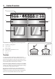
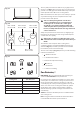
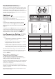
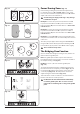
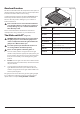
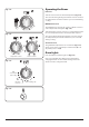
Table Of Contents
- 1. Before You Start...
- 2. Cooker Overview
- The Hob
- Pan Detector,
- Residual Heat Indicator, H
- Child Lock, 
- Low Temperature Setting, L1/L2/L3
- Power Boost Setting, P
- Power Sharing Zones (Fig. 2.8)
- The Bridging-Zone Function
- Overheat Function
- The Glide-out Grill™ (Fig. 2.14)
- The Ovens
- The Multifunction Oven
- Multifunction Oven Functions
- The Fan Oven
- The Slow Cook Oven
- Operating the Ovens
- Oven Lights
- Accessories
- 3. Using the Glide-out Grill™
- 4. 3 Button clock
- 5. Cooking Tips
- 6. Cooking Table
- 7. Cleaning Your Cooker
- 8. Troubleshooting
- 9. Service and Spares
- 10. Installation
- Dear Installer
- Safety Requirements and Regulations
- Provision of Ventilation
- Location of Cooker
- Positioning the Cooker
- Moving the Cooker
- Lowering the Two Rear Rollers
- Completing the Move
- Fitting the Stability Bracket
- Repositioning the Cooker Following Connection
- Levelling
- Electrical Connection
- Connection in New Zealand
- Fixed Wiring
- Final Fitting and Checks
- Customer Care
- 11. Servicing
- 12. Circuit Diagrams
- 13. Technical Data

12
Power Sharing Zones (Fig. 2.8)
Power sharing is taking the power from the adjacent zone.
For example, if zones C, D and E (Fig. 2.8) are set to power
level 9, or set to Power Boost (P) the power level in D or E will
adjust in the order it was switched on.
n
Avoid heating an empty pan. Doing so may damage
both the hob and pan.
Example 1: Set zone C to power level 9, switch on zone D
to power level 9 and then zone E to power level 9. After a
few seconds zone D power level will reduce to 7. Zone C will
remain at P or 9
Example 2: Set zone C to power level 9, switch on zone E
to power level 9 and then zone D to power level 9. After a
few seconds zone E power level will reduce to 6. Zone C will
remain at P or 9
Example 3: Set zone D and E to power level 9 and then zone
C to power level 9. After a few seconds zone E power level will
reduce to 6.
The same principle applies when using zone A and B. When
using zone A on Power Boost (P) and then switching zone B
to Power Boost (P), the power to zone A will reduce slightly.
n
This is a built-in safety device.
The Bridging-Zone Function
Zones A and B can be bridged, creating an area, ideal for use
with an induction griddle plate.
Note: The griddle plate should comprise of an induction
friendly, at bottom, large enough to cover zones A and B of
the hotplate heating area (Fig. 2.9).
DO NOT use zones C, D or E to heat the griddle plate
(Fig. 2.10).
To activate the dualzone function, simultaneously turn the
two left-hand controls completely clockwise (Fig. 2.11) and
hold until the [ ] symbols appear in the centre of the hob
control display (Fig. 2.12). The temperature can then be
adjusted using the left-hand knob (Fig. 2.13).
Turn both knobs counter-clockwise to cancel the dualzone
function and return to normal operation.
n
DO NOT turn the two left-hand knobs individually
to heat the griddle plate. This can cause excessive
temperatures and damage the coating on the griddle
plate.
Fig. 2.8
Fig. 2.9
Fig. 2.10
Fig. 2.11
Fig. 2.12
Fig. 2.13
A
B
C
E
D
A & B linked
C, D & E linked
A
B
C
E
D
M
M