USER GUIDE & INSTALLATION INSTRUCTIONS Nexus SE 110 Induction Australia U111098 - 01
Contents 1. 2. Before You Start... 1 7. Cleaning Your Cooker 23 Personal Safety 1 Hob 23 Electrical Connection Safety 2 Glide-out Grill™ 24 Peculiar Smells 3 Control Panel and Doors 25 Ventilation 3 Ovens 25 Maintenance 3 Cleaning Table 26 Induction care 4 Grill/Glide-out Grill™ Care 7 Cooling Fan 7 Cooker Care 7 Cleaning 8 Cooker Overview 9 8. Troubleshooting 27 9. Service and Spares 30 10.
ii
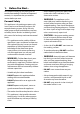
1. Before You Start... Your cooker should give you many years of trouble-free cooking if installed and operated correctly. It is important that you read this section before you start. Personal Safety • DO NOT operate this appliance before reading the instruction booklet. • DO NOT place articles on or against this appliance. • DO NOT operate with panels, covers or guards removed from this appliance. • The cooker should not be placed on a base.
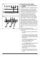
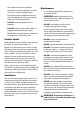
Electrical Connection Safety Fig. 1.1 WARNING: THE APPLIANCE MUST BE nn EARTHED. The cooker is preset for a single-phase earthed electrical connection. It is essential to install a multi-pole circuit breaker that completely disconnects the appliance from the mains, with a minimum contact break distance of 3 mm. ArtNo.132-0001 - 1 phase 240Vac 50Hz 1-phase 230 VAC 50 Hz The total electrical load of the appliance is approximately 15 kW.
• The appliance must be installed in accordance with the regulations in force and only in a well ventilated space. Maintenance • It is recommended that this appliance is serviced annually. • Failure to install the appliance correctly could invalidate any warranty or liability claims and lead to prosecution. • • DO NOT install the appliance on a platform. WARNING: Before replacing the bulb, turn off the power supply and make sure that the oven is cool.
NEVER try to extinguish a fire with water, nn but switch off the appliance and then Induction care • cover the flame e.g. with a lid or a fire blanket. • NEVER leave a chip pan unattended. Always heat fat slowly, and watch as it heats. Deep fry pans should be only one third full of fat. • WARNING: Danger of fire: do not store of this hob comply with the applicable European standards on electromagnetic interference.
• Take care NOT to scratch the surface when placing cookware on the glass panel. • Only certain types of glass, glass-ceramic, earthenware or other glazed containers are suitable for hotplate cooking; others may break because of the sudden change in temperature. NEVER cook directly on the hob surface (Fig. 1.4). Fig. 1.3 Fig. 1.4 Fig. 1.5 • DO NOT leave the hob zones switched on ArtNo.312-0001 Not cooking surface unless being used for cooking. • DO NOT stand or rest heavy objects on the hob.
Fig. 1.8 • We recommend that you avoid wiping any surface unit areas until they have cooled and the indicator light has gone off. Sugar spills are the exception to this (see ‘Cleaning your Cooker’). After cleaning, use a dry cloth or paper towel to remove any cleaning cream residue. • The ceramic surface should be washed after use in order to prevent it from becoming scratched or dirty. However, you should clean the hob with caution as some cleaners can produce noxious fumes if applied to a hot surface.
• • • Make sure the shelves are pushed firmly to the back of the oven. DO NOT close the door against the oven shelves. DO NOT use aluminium foil to cover shelves, linings or the oven roof. When the oven is on, DO NOT leave the oven door open for longer than necessary, otherwise the control knobs may become very hot. • DO NOT use the timed oven if the adjoining oven is already warm. • DO NOT place warm food in the oven to be timed. • DO NOT use a timed oven that is already warm.
Cleaning • Isolate the electricity supply before carrying out any thorough cleaning. Allow the cooker to cool. • In the interests of hygiene and safety, the cooker should be kept clean at all times as a build up in fats and other food stuff could result in a fire. • Clean only the parts listed in this guide. • Clean with caution. If a wet sponge or cloth is used to wipe spills on a hot surface, be careful to avoid steam burns. Some cleaners can produce noxious fumes if applied to a hot surface.
2. Cooker Overview Fig. 2.1 A B M C E D F Your induction cooker (Fig. 2.1) has the following features: A. 5 induction cooking zones B. Control panel C. Glide-out grill D. Programmable multifunction oven E. Slow cook oven F. Fan oven Fig. 2.2 The Hob Use only pans that are suitable for induction hobs. We recommend stainless steel, enamelled steel pans or cast iron pans with enamelled bases.
The very best pans have bases that are very slightly curved up when cold (Fig. 2.3). If you hold a ruler across the bottom you will see a small gap in the middle. When they heat up the metal expands and lies flat on the cooking surface. Fig. 2.3 Make sure that the base of the pan is clean and dry to prevent any residue burning onto the hob panel. This also helps prevent scratches and deposits. Take care when placing hot lids onto the hob nn surface. Lids that have been covering boiling or Fig. 2.
Residual Heat Indicator, H Fig. 2.6 After use, a cooking zone will remain hot for a while as heat dissipates. When a cooking zone is switched off the residual heat indicator symbol [H ], will appear in the display. This shows that the cooking zone temperature is above 60 °C and may still cause burns. Once the temperature has dropped to below 60 °C the [H ] will go out. M Child Lock, M IMPORTANT: The child lock can only be activated when all the cooking zones are switched off.
Power Sharing Zones (Fig. 2.8) A & B linked Fig. 2.8 Power sharing is taking the power from the adjacent zone. For example, if zones C, D and E (Fig. 2.8) are set to power level 9, or set to Power Boost (P) the power level in D or E will adjust in the order it was switched on. D A C B E Avoid heating an empty pan. Doing so may damage nn both the hob and pan. Example 1: Set zone C to power level 9, switch on zone D to power level 9 and then zone E to power level 9.
Overheat Function Fig. 2.14 This function identifies when the temperature of the pan rises rapidly and works to maintain a safe level of pan temperature. It should not interfere with normal cooking. Cookware with bases that become distorted (Fig. 2.2) when heated may interfere with the operation of the Overheat Function. This may result in damage to your cookware or Induction Glass Hob. Please remember not to leave the hob unattended. nn Care should be taken to not allow your cookware to boil dry.
The Ovens Fan Oven This function operates the fan and the heating element around it. An even heat is produced throughout the oven, allowing you to cook large amounts quickly. The clock must be set to the time of day before the left-hand oven will work. See the following section on ‘The Clock’ for instructions on setting the time of day. References to ‘left-hand’ and ‘right-hand’ ovens apply as viewed from the front of the appliance.
The Fan Oven Conventional Oven (Top and Base Heat) This function combines the heat from the top and base elements. It is particularly suitable for roasting and baking pastry, cakes and biscuits. Fan ovens circulate hot air continuously, which means faster, more even cooking. The recommended cooking temperatures for a fan oven are generally lower than those for a non-fan oven.
Operating the Ovens Fig. 2.15 Fan Oven Turn the oven knob to the desired temperature (Fig. 2.15). The oven indicator light will glow until the oven has reached the temperature selected. It will then cycle on and off during cooking. Multifunction Oven The multifunction oven has two controls: a function selector and a temperature setting knob (Fig. 2.16). Turn the function selector control to a cooking function. Turn the oven temperature knob to the temperature required. Fig. 2.
Accessories Fig. 2.19 Shelf guard Glide-out Shelves The oven shelves (Fig. 2.19) are retained when pulled forward but can be easily removed and refitted. Both ovens are supplied with glide-out oven shelves. To fit the glide-out shelves, hook the front of the shelf onto the runners as shown (Fig. 2.20). The rear of the shelf should rest on the runners, in front of the rear stop (Fig. 2.20). Front The glide-out shelves and runners can be easily removed or repositioned. Fig. 2.
3. Using the Glide-out Grill™ DocAUS.020-0004 - Overview - 110DF - Elan Fig. 3.2 Fig. 3.1 Nearest to the element Middle High Middle Low Furthest from the element Four grill height positions refer to Fig. 3.5 Fig. 3.4 Fig. 3.3 To switch on both elements To switch on the right half element Fig. 3.5 Four grill height positions Nearest to the element Middle High 180o Cooking suggestions Furthest from the element 180o Middle Low 180o 180o 1. Nearest to the element – Toast, streaky bacon. 2.
4. 3 Button clock Using the clock Fig. 4.1 You can use the clock to turn the programmable oven on and off. The clock must be set to the time of day before the oven will work. NOTE: When using the timer functions, first set the clock as required before setting the oven temperature. ArtNo.306-0001 - 3-button clock The oven can be switched on when the cook symbol [ ] is displayed. This symbol remains visible during normal operation. Fig. 4.2 Setting the clock 1. 2. The LCD clock is shown in (Fig. 4.
Fig. 4.7 3. When the ‘stop time’ is reached an alarm will sound and the oven will stop working. The word ‘AUTO’ will flash on the display (Fig. 4.6). 4. Press any button to stop the alarm and return to manual cooking. If the alarm is not stopped, it will stop automatically after 7 minutes. ArtNo.306-0001 - 3-button clock To start and then stop the programmable oven Set the programmable oven to automatically start and stop using a combination of the ‘cook period’ and ‘stop time’. Fig. 4.
5. Cooking Tips Hints on Using Your Induction Cooker General Oven Tips If you have not used an induction cooker before please be aware of the following: The wire shelves should always be pushed firmly to the back of the oven. • Make sure that the pans you have or buy are suitable for use on the induction hob. Stainless steel, enamelled steel or cast iron is ideal. Double check before you buy pans – they must have bases that would attract a magnet.
6. Cooking Table The oven control settings and cooking times given in the table below are intended to be used as a guide only. Individual tastes may require the temperature to be altered to provide a preferred result. Food is cooked at lower temperature in a fan oven than in a conventional oven. When using recipes, reduce the fan oven temperature by 10 °C and the cooking time by 5-10 minutes. The temperature in the fan oven does not vary with height in the oven so you can use any shelf.
7. Cleaning Your Cooker Isolate the electricity supply before carrying out any major cleaning. Allow the cooker to cool. Fig. 7.1 NEVER use paint solvents, washing soda, caustic nn cleaners, biological powders, bleach, chlorine based bleach cleaners, coarse abrasives or salt. DO NOT mix different cleaning products – they may nn react together with hazardous results. All parts of the cooker can be cleaned with hot soapy water. Take care that no surplus water seeps into the appliance.
Glide-out Grill™ Fig. 7.2 The grill pan and trivet should be washed in hot soapy water. Alternatively, the grill pan can be washed in a dishwasher. After grilling meats or any foods that soil, leave to soak for a few minutes immediately after use. Stubborn particles may be removed from the trivet using a nylon brush. Before you remove any of the grill parts for cleaning, nn make sure that they are cool, or use oven gloves. DO NOT use any abrasive substances. nn Removing the Glide-out Grill Pan Fig. 7.
Control Panel and Doors Fig. 7.6 Avoid using any abrasive cleaners, including cream cleaners. For best results, use a liquid detergent. The same cleaner can also be used on the doors. Alternatively, use a soft cloth wrung out in clean hot soapy water. You can use the same method for cleaning the control panel and knobs. After cleaning, polish with a dry cloth. Glass Fronted Door Panels ArtNo.
Cleaning Table Cleaners listed (Table 7.1) are available from supermarkets or electrical retailers as stated. For enamelled surfaces use a cleaner that is approved for use on vitreous enamel. Regular cleaning is recommended. For easier cleaning, wipe up any spillages immediately. Hotplate Part Finish Recommended Cleaning Method Hob top Enamel or stainless steel Hot soapy water, soft cloth. Any stubborn stains remove gently with a nylon scourer.
8. Troubleshooting DocNo.050-0001 - Troubleshooting - Induction GENERIC Interference with and repairs to the hob MUST NOT nn be carried out by unqualified persons. Do not try The cooling fan The induction hob incorporates a cooling fan. This cooling fan is active when either the grill or the oven(s) are on. Under certain conditions, the cooling fan may remain active when the grill or oven(s) are switched off. This is normal and the fan will switch off automatically.
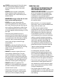
Food is cooking too slowly, too quickly, or burning Fig. 8.1 Cooking times may differ from your previous oven. Check that you are using the recommended temperatures and shelf positions – see the oven cooking guide. Then adjust the settings according to your own individual tastes. The oven light is not working The bulb has probably blown. You can buy a replacement bulb (which is not covered under the guarantee) from most electrical stores. Fig. 8.2 Ask for a 40 W - 230 V halogen lamp (G9) (Fig. 8.1).
Power failure In the event of a failure in the electrical supply, remember to reset the clock so that the timed oven continues to operate. The timed oven is not coming on when turned on manually Is the power on? Is the clock illuminated? If not, there may be something wrong with the power supply.
INSTALLATION Check the appliance is electrically safe when you have finished. 9. Service and Spares Firstly, please complete the appliance details below and keep them safe for future reference – this information will enable us to accurately identify the particular appliance and help us to help you. Filling this in now will save time and inconvenience if you later have a problem with the appliance. It may also be of benefit to keep your purchase receipt with this leaflet.
INSTALLATION Check the appliance is electrically safe when you have finished. 10. Installation Dear Installer Location of Cooker Before you start your installation, please complete the details below, so that, if your customer has a problem relating to your installation, they will be able to contact you easily. The cooker may be installed in a kitchen/kitchen diner but NOT in a room containing a bath or shower.
INSTALLATION Check the appliance is electrically safe when you have finished. Positioning the Cooker Fig. 10.1 75 mm min 650 mm min Fig. 10.1 and Fig. 10.2 show the minimum recommended distance from the cooker to nearby surfaces. 75 mm min The cooker should not be placed on a base. Fig. 10.1 and Fig. 10.2 Cookers installed into recess: The cooker must have side clearance ABOVE hob level of 75mm up to a height of 410mm. This can be reduced to 25mm if the surface of the side wall is non-combustible.
INSTALLATION Check the appliance is electrically safe when you have finished. Lowering the Two Rear Rollers Fig. 10.5 To adjust the height of the rear of the cooker, first fit a 13 mm spanner or socket wrench onto the hexagonal adjusting nut (Fig. 10.5). Rotate the nut – clockwise to raise – counter-clockwise to lower. Make 10 complete (360°) turns clockwise. Make sure you lower BOTH REAR ROLLERS. Completing the Move Unfold the rear edge of the cardboard base tray.
INSTALLATION Check the appliance is electrically safe when you have finished. Electrical Connection Current Operated Earth Leakage Breakers This appliance must be installed by a qualified electrician to comply with with current AS/NZS 3000 Wiring Rules and regulations in force.
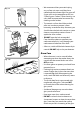
INSTALLATION Check the appliance is electrically safe when you have finished. Fixed Wiring Fig. 10.13 DISCONNECT FROM THE MAINS SUPPLY. nn For connection to fixed wiring, i.e. flexible conduit, remove the electrical terminal cover on the back panel (Fig. 10.13). Fit the conduit box to the cooker using the two M5 screw fittings located at the top of the box. Remove the M4 screw from the base, and fix to the cooker, via the fitting through the back of the conduit box (Fig. 10.14).
INSTALLATION Check the appliance is electrically safe when you have finished. Final Fitting and Checks Fig. 10.17 Hob Check Check each cooking zone in turn. Be sure to use pans of the correct size and material. Grill Check Turn on the grill control and check that the grill heats up. Oven Check Set the clock as described earlier, and then turn on the ovens. Check the oven fans start to turn and that the ovens heat up. ArtNo.
WARNING – SERVICING TO BE CARRIED OUT ONLY BY AN AUTHORISED PERSON Disconnect from electricity before servicing. Check appliance is safe when you have finished. 11. Servicing 3. Controls Disconnect the cooker from the electricity supply nn before servicing, particularly before removing any 3.1 To Replace the Light Switch of the following: control panel, side panels, ceramic hob, or any of the electrical components or cover boxes. DISCONNECT FROM ELECTRICITY SUPPLY. nn Remove the control panel (see 1.
WARNING – SERVICING TO BE CARRIED OUT ONLY BY AN AUTHORISED PERSON Disconnect from electricity before servicing. Check appliance is safe when you have finished. 4. Grill 4.1 To Replace the Grill Controller DISCONNECT FROM ELECTRICITY SUPPLY. nn Lift up the hob and remove the control panel (see 1.1 and 2.1). Disconnect the wiring from the controller. Remove the two screws holding the controller to the mounting panel. Fit the new controller and reassemble in reverse order. Check for correct operation. 4.
WARNING – SERVICING TO BE CARRIED OUT ONLY BY AN AUTHORISED PERSON Disconnect from electricity before servicing. Check appliance is safe when you have finished. 5.3 To Remove an Oven Inner Back Fig. 11.1 DISCONNECT FROM ELECTRICITY SUPPLY. nn Open the door and remove the shelves. Remove the screws and washers securing the inner back to the back of the oven (Fig. 11.1). Carefully lift away the inner back. Reassemble in reverse order making sure that the screws and washers are fully tightened. 5.
WARNING – SERVICING TO BE CARRIED OUT ONLY BY AN AUTHORISED PERSON Disconnect from electricity before servicing. Check appliance is safe when you have finished. Fig. 11.3 6. Doors Fig. 11.4 6.1 To Remove the Grill Door Remove the left-hand side panel (see 1.2). Remove the control panel (see 1.1). Remove the centre cover strip (5 screws, 2 top, 2 bottom, 1 in middle). Remove the two countersunk screws (1 each side) securing the grill hinge arms to the front of the grill chamber. 2 1 ArtNo.
WARNING – SERVICING TO BE CARRIED OUT ONLY BY AN AUTHORISED PERSON Disconnect from electricity before servicing. Check appliance is safe when you have finished. 6.6 To Adjust the Main Oven Door Catch Keep Fig. 11.10 Open the oven door, and slacken off the locknut at the base of the keep (Fig. 11.9). Screw in or out as required until the required fit is obtained. Retighten the locking nut. 6.7 To Replace an Oven Door Seal Open the oven door.
12. Circuit Diagrams Hob INDUCTION UNIT E Earth 5 N(6) On Terminal Block 4 N(4) On Terminal Block 3 2 1 HOB DISPLAY w/br w/br L(2) L(3) On Terminal Block 1 INTERFACE 2 BOARD 5 3 4 w/br w/br 1 2 w/br 5 3 4 Key The connections shown in the circuit diagram are for single-phase. The ratings are for 230 V 50 Hz.
Oven r r X07 r bk X02 X26 b br X26 bk b br X03 b b b X04 v b bk b X27 b X01 r P2 1 v v P1 I b X27 X08 X10 X11 w b r w b X32 br bk X05 b r o r w y o X16 7 v P7 r 6 P6 5 P5 P4 P3 2 P2 1 P1 r w X26 Y X14 2 P2 1 P1 v X15 br P095199 b P038434 P2 P1 1 X31 br b bk r r 2 o X18 y y r r 2 1 y y X12 r y P095199 br y X24 P8 w 4 y 3 o bk X26 y X06 gr 8 gr X09 b br y v br b r r 2 X26 bk v r X17 v v v v 4 P095199 o br
13. Technical Data INSTALLER: Please leave these instructions with the user. DATA BADGE LOCATION: Cooker back, serial number repeater badge below the oven door opening. COUNTRY OF DESTINATION: Australia. Connections Electric 230 / 400 V ~ 50 Hz 3N Dimensions Model NEXUS SE 110 Induction Overall height maximum 930 mm minimum 905 mm Overall width 1100 mm Overall depth 608 mm excluding handles, 646 mm including handles Minimum height above the hotplate 650 mm Refer to 'Positioning the Cooker'.
NOTE 45
NOTE 46
NOTE 47
Clarence Street, Royal Leamington Spa, Warwickshire, CV31 2AD, England. www.falconworld.