
User's Manual
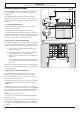
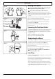
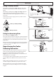
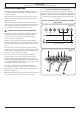
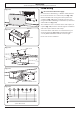
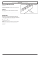
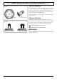
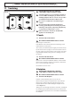
Table Of Contents
- 1. Before You Start...
- 2. Cooker Overview
- 3. Using the Glide-out Grill™
- 4. 3 button clock
- 5. Cooking Table
- 6. Cleaning your cooker
- 7. Troubleshooting
- 8. Service and Spares
- 9. Installation
- Safety Requirements and Regulations
- Provision of Ventilation
- Location of Cooker
- Conversion
- Positioning the Cooker
- Moving the Cooker
- Lowering the Two Rear Rollers
- Completing the Move
- Levelling
- Repositioning the Cooker Following Connection
- Gas Connection
- Natural Gas
- Propane
- Pressure Testing
- Electrical Connection
- Fixed Wiring
- Final Fitting and Checks
- 10. Conversion to LP Gas
- 11. Servicing
- 12. Circuit Diagram
- 13. Technical Data

INSTALLATION
Check the appliance is gas sound when you have nished.
32
Fixed Wiring
n
Disconnect from the mains supply.
For connection to xed wiring, i.e. exible conduit, Remove
the electrical terminal cover on the back panel (Fig. 9.14).
Remove the M4 screw securing the reducer plates to the
conduit box (Fig. 9.15). Fit the conduit box to the cooker
using the two M5 screw ttings located at the top of the box
and the M4 screw (Fig. 9.16).
The conduit box cover is reversible. Fit the reducer plates, if
required (Fig. 9.17). Feed the cable through the conduit box
and secure in place with the cable clamp.
Connect the mains cable to the correct terminals for your
electrical supply type (Fig. 9.18). Check that the links are
correctly tted and that the terminal screws are tight.
Fit the cover to the conduit box.
Conduit box
M4 screw
M5 screws
Reducer plates
M4 screw
Reducer plates
Reversible conduit box cover
ArtNo.132-0002 - 3 phase 240/415Vac 50Hz
3-phase 400 V
AC
50 Hz
Fig. 9.14
Fig. 9.15
Fig. 9.16
Fig. 9.17
Fig. 9.18