USER GUIDE & INSTALLATION INSTRUCTIONS Nexus 90 Dual Fuel U111292 - 02
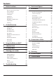
Contents 1. 2. 3. 1 8. Service and Spares 24 Personal Safety 1 Electrical Connection Safety 2 9. Installation 25 If You Smell Gas 2 Peculiar Smells 2 Cooling Fan 2 Ventilation 3 Maintenance 3 Grill/Glide-out Grill™ Care 5 Cooker Care 5 Cleaning 5 Before You Start...
ii
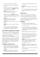
1. Before You Start... Your cooker should give you many years of trouble-free cooking if installed and operated correctly. It is important that you read this section before you start. Personal Safety This appliance is for cooking purposes only. It must not be used for other purposes, for example heating a room. Using it for any other purpose could invalidate any warranty or liability claim. Besides invalidating claims this wastes fuel and may overheat the control knobs.
• DO NOT use a steam cleaner on your cooker. • Always keep combustible materials, e.g. curtains, and flammable liquids a safe distance away from the cooker. • Make sure that the gas supply is turned on and that the cooker is wired in and switched on. • DO NOT spray aerosols in the vicinity of the cooker while it is on. • In your own interest and that of safety, it is law that all gas appliances be installed by a qualified person(s).
the grill or ovens are in operation the fan will run to cool the fascia and control knobs. by the manufacturer of the cooking appliance or indicated by the manufacturer of the appliance in the instructions for use as suitable or hob guards incorporated in the appliance. The use of inappropriate guards can cause accidents. Ventilation The use of a cooking appliance results in the production of heat and moisture in the room in which it is installed.
along the back of the cooker) for warming plates, dishes, drying tea towels or softening butter. Fig. 1.1 • DO NOT use water on grease fires and never pick up a flaming pan. Turn the controls off and then smother a flaming pan on a surface unit by covering the pan completely with a well fitting lid or baking tray. If available, use a multi-purpose dry chemical or foam-type fire extinguisher. • DO NOT modify this appliance.
door glass since they can scratch the surface, which may result in shattering of the glass. • underneath it, otherwise the knobs may become hot. Make sure the shelves are pushed firmly to the back of the oven. DO NOT close the door against the oven shelves. • DO NOT use aluminium foil to cover shelves, linings or the oven roof. • When the oven is on, DO NOT leave the oven door open for longer than necessary, otherwise the control knobs may become very hot.
6 • Before you remove any of the grill parts for cleaning, make sure that they are cool or use oven gloves. • DO NOT use any abrasive substances on the grill and grill parts. • DO NOT put the side runners in a dishwasher. • DO NOT put the burner heads in a dishwasher. • NEVER use caustic or abrasive cleaners as these will damage the surface. • DO NOT use steel wool, oven cleaning pads or any other materials that will scratch the surface. • NEVER store flammable materials in the drawer.
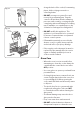
2. Cooker Overview Fig. 2.1 A B C E D The 90 dual fuel cooker (Fig. 2.1) has the following features: Fig. 2.2 A. 4 hotplate burners and a Wok Burner B. Control Panel C. Glide-out Grill™ with 4 position Trivet D. Multifunction Oven E. Fan Oven Hotplate Burners The labels by each of the control knobs indicates which area that knob controls. Each burner has a Flame Supervision Device (FSD) that prevents the flow of gas if the flame goes out.
If and when you let go of the control knob or the burner goes out, then the FSD has not been bypassed. Turn the control knob to the OFF position and wait for one minute before you try again, this time making sure to hold in the control knob for slightly longer. Fig. 2.3 Adjust the flame height to suit by turning the knob counterclockwise (Fig. 2.3). On this cooker the low position is beyond high, NOT between high and off.
The Griddle Plate Fig. 2.12 The griddle plate fits the left-hand pan support, front to back (Fig. 2.12). It is designed for cooking food on directly. DO NOT use pans of any kind on it. The griddle plate surface is non-stick and metal cooking utensils (e.g. spatulas) will damage the surface. Use heat resistant plastic or wooden utensils. n Do not put it crossways – it will not fit properly and will be unstable (Fig. 2.13).
The Ovens The clock must be set to the time of day before the left hand oven will work. See the following section on ‘The Clock’ for instructions on setting the time of day. References to ‘left-hand’ and ‘right-hand’ ovens apply as viewed from the front of the appliance. The left-hand oven is a multifunction oven, while the righthand oven is a fan oven.
Multifunction Oven Functions Fan Assisted Oven This function operates the fan, circulating air heated by the elements at the top and the base of the oven. The combination of fan and conventional cooking (top and base heat) makes this function ideal for cooking large items that need thorough cooking, such as a large meat roast. Defrost This function operates the fan to circulate cold air only. Make sure the temperature control is at 0°C and that no heat is applied.
Fan Oven Fig. 2.16 The right-hand oven is a fan oven that circulates hot air continuously, which means faster, more even cooking. The recommended cooking temperatures for a fan oven are generally lower than a conventional oven. Note: Please remember that all cookers vary so temperatures in your new ovens may differ to those in your previous cooker.
To remove the glide-out runners Fig. 2.21 Twist to unclip the base of the runners from the shelf supports. Then unhook the runner from the top rung of the shelf support and remove (Fig. 2.22). Front bracket Rear stop To refit the glide-out runners Hook the rear of the runner over the top rung of a pair of shelf supports. Then hook the front of the runner onto the same rung. Push to clip under the bottom rung (Fig. 2.23). Ensure that the shelf runners are fitted in the same position on each side (Fig.
3. Using the Glide-out Grill™ DocAUS.020-0004 - Overview - 110DF - Elan Fig. 3.2 Fig. 3.1 Nearest to the element Middle High Middle Low Furthest from the element Four grill height positions refer to Fig. 3.5 Fig. 3.4 Fig. 3.3 To switch on both elements To switch on the right half element Four grill height positions Nearest to the element Fig. 3.5 Middle High 180o Cooking suggestions Furthest from the element 180o Middle Low 180o 180o 1. Nearest to the element – Toast, streaky bacon. 2.
4. 3 button clock Setting the time The clock must be set to the time of Reset the minute minder day before the oven will work Step. 1 Note: The cook symbol [ ] remains visible during normal operation. Step. 1 ArtNo.306-0001 - 3-button clock ArtNo.306-0001 - 3-button clock Step. 2 Step. 2 Press the [+] and [-] buttons simultaneously. Press either [+] or [-] buttons. ArtNo.306-0001 - 3-button clock ArtNo.
To start and stop the oven automatically AUTO is showing, but you want to revert to manual cooking (main oven only) (main oven only) Step. 1 Press [M] button again until current time is diplayed. Press either [+] or [-] buttons ArtNo.306-0001 - 3-button clock Step. 2 ArtNo.306-0001 - 3-button clock Set the length of time you want the oven to cook for. ArtNo.306-0001 - 3-button clock Changing the frequency of the alarm Step. 1 Press [M] button again until current time is diplayed.
5. Cooking Table The oven control settings and cooking times given in the table below are intended to be used as a guide only. Individual tastes may require the temperature to be altered to provide a preferred result. Food is cooked at lower temperature in a fan oven than in a conventional oven. When using recipes, reduce the fan oven temperature by 10 °C and the cooking time by 5-10 minutes. The temperature in the fan oven does not vary with height in the oven so you can use any shelf.
6. Cleaning your cooker Essential Information Fig. 6.1 Isolate the electricity supply before carrying out any thorough cleaning. Allow the cooker to cool. n n A C NEVER use paint solvents, washing soda, caustic cleaners, biological powders, bleach, chlorine based bleach cleaners, coarse abrasives or salt. B DO NOT mix different cleaning products – they may react together with hazardous results.
The Griddle Plate Fig. 6.5 Always clean the griddle plate after use. Allow it to cool completely before removing. Immerse the griddle plate in hot soapy water. Use a soft cloth or, for stubborn stains, a nylon washing up brush. NOTE: If the griddle plate is washed in a dishwasher then some dishwasher residue may appear on the back. This is normal and will not affect the performance of your griddle plate. Glide-out Grill Fig. 6.6 ArtNo.
Glass Fronted Door Panels Fig. 6.9 The oven door front panels can be taken off so that the glass panels can be cleaned. Move the cooker forward to gain access to the sides (see the ‘Moving the Cooker’ section under ‘Installation’). Open the oven door slightly and remove the front panel fixing screws from the door sides, two each side (Fig. 6.9). Carefully lift off the outer door panel. The inside face of the glass panels can now be cleaned – take care not to disturb or wet the door insulation. ArtNo.
Cleaning table Cleaners listed are available from supermarkets or electrical retailers as stated. For enamelled surfaces use a cleaner that is approved for use on vitreous enamel. Regular cleaning is recommended. For easier cleaning, wipe up any spillages immediately. Hotplate Part Finish Recommended Cleaning Method Hob top (including burner heads and caps) Enamel, stainless steel, aluminium Hot soapy water, soft cloth. Any stubborn stains remove gently with a nylon scourer.
7. Troubleshooting Hotplate/Cooktop ignition or hotplate burners faulty Food is cooking too slowly, too quickly, or burning Is the power on? Is the clock illuminated? Cooking times may differ from your previous oven. If not, there maybe something wrong with the power supply. Check that you are using the recommended temperatures and shelf positions – see the oven cooking guide. The oven control settings and cooking times are intended to be used only as a guide.
Oven light is not working Fig. 7.1 The bulb has probably burnt out. You can buy a replacement bulb (which is not covered under the warranty) from a good electrical shop. Ask for a 40 W - 230 V halogen lamp (G9) (Fig. 7.1). Turn off the power at the circuit breaker. Before removing the existing bulb, turn off the power supply and make sure that the oven is cool. Open the oven door and remove the oven shelves. Fig. 7.2 Remove the bulb cover by turning it a quarter turn, counterclockwise.
INSTALLATION Check the appliance is electrically safe when you have finished. 8. Service and Spares Firstly, please complete the appliance details below and keep them safe for future reference – this information will enable us to accurately identify the particular appliance and help us to help you. Filling this in now will save time and inconvenience if you later have a problem with the appliance. It may also be of benefit to keep your purchase receipt with this leaflet.
INSTALLATION Check the appliance is gas sound when you have finished. 9. Installation Safety Requirements and Regulations Provision of Ventilation This appliance is not connected to a combustion products evacuation device. Particular attention shall be given to the relevant requirements regarding ventilation. You must be aware of the following safety requirements & regulations.
INSTALLATION Check the appliance is gas sound when you have finished. 3 pan supports ArtNo.000-0001 90 Pan supports Griddle plate (Supplied) You will need the following equipment to complete the cooker installation satisfactorily: Wok cradle (Supplied) • * Restraining chain and hook: If the cooker is to be supplied with gas through a flexible hose, a restraining chain and hook MUST be fitted. These are not supplied with the cooker but are available at most builders’ merchants. ArtNo.
INSTALLATION Check the appliance is gas sound when you have finished. Positioning the Cooker Fig. 9.1 The diagram (Fig. 9.1) shows the minimum recommended distance from the cooker to nearby surfaces as given in AS/NZS 5601. *Any splashback must be fitted in accordance with the manufacturers instructions. Allowance should be made for the additional height of the flue trim, which is fitted to the cooker hob. E Hob D A B * C 1.
INSTALLATION Check the appliance is gas sound when you have finished. Moving the Cooker Fig. 9.3 n On no account try and move the cooker while it is plugged into the electricity supply. n The cooker is very heavy, so take extra care. We recommend that two people manoeuvre the cooker. Make sure that the floor covering is firmly fixed, or removed, to prevent it being disturbed when moving the cooker around.
INSTALLATION Check the appliance is gas sound when you have finished. Fitting a Stability Bracket Fig. 9.7 When fitting a stability bracket (Fig. 9.7) please refer to the instructions supplied with the bracket for further details on fitting. When fitting a stability bracket (Fig. 9.8 and Fig. 9.9) adjust the bracket to give the smallest practicable clearance between the bracket and the engagement slot in the rear of the cooker.
INSTALLATION Check the appliance is gas sound when you have finished. Gas Connection Fig. 9.11 This must be in accordance with the relevant standards. 675 Gas inlet 315 The gas supply needs to terminate with a down-facing threaded fitting ½” connection. The inlet connector is located just below the hotplate level at the rear of the cooker. A Because the height of the cooker can be adjusted and each connection is different, it is difficult to give precise dimensions.
INSTALLATION Check the appliance is gas sound when you have finished. Electrical Connection Current Operated Earth Leakage Breakers This appliance must be installed by a qualified electrician to comply with with current AS/NZS 3000 Wiring Rules and regulations in force. The combined use of your cooker and other domestic appliances may cause nuisance tripping, so we recommend that the cooker is protected on an individual RCD (Residual Current Device) or RCBO (Residual Current Breaker with Overload).
INSTALLATION Check the appliance is gas sound when you have finished. Fixed Wiring Fig. 9.14 n Disconnect from the mains supply. For connection to fixed wiring, i.e. flexible conduit, Remove the electrical terminal cover on the back panel (Fig. 9.14). Remove the M4 screw securing the reducer plates to the conduit box (Fig. 9.15). Fit the conduit box to the cooker using the two M5 screw fittings located at the top of the box and the M4 screw (Fig. 9.16). The conduit box cover is reversible.
INSTALLATION Check the appliance is gas sound when you have finished. Final Fitting and Checks Fig. 9.19 Hob Check Check each cooking zone in turn. Be sure to use pans of the correct size and material. Grill Check Turn on the grill control and check that the grill heats up. Oven Check x 2 positions Set the clock as described earlier, and then turn on the ovens. Check the oven fans start to turn and that the ovens heat up. ArtNo.
WARNING – SERVICING TO BE CARRIED OUT ONLY BY AN AUTHORISED PERSON Disconnect from electricity and gas before servicing. Check appliance is safe when you have finished. 10. Conversion to LP Gas Conversion from Natural Gas (1.0 kPa) to LPG X Propane (2.54 kPa) n A suitably competent person must perform the conversion. After conversion the installation must comply with the relevant regulations and also the local electricity supply company requirements.
WARNING – SERVICING TO BE CARRIED OUT ONLY BY AN AUTHORISED PERSON Disconnect from electricity and gas before servicing. Check appliance is safe when you have finished. Set the Governor Fig. 10.3 Unscrew the governor’s brass top. In the base of the brass top is a plastic snap-in converter device (Fig. 10.3). To convert the governor, snap the device out of the top and refit it the other way round. The snap-in converter device is marked to show the gas for which it is set (Fig. 10.4). ArtNo.
WARNING – SERVICING TO BE CARRIED OUT ONLY BY AN AUTHORISED PERSON Disconnect from electricity before servicing. Check appliance is safe when you have finished. 11. Servicing Fig. 11.1 n BEFORE SERVICING ANY GAS CARRYING COMPONENTS TURN OFF THE GAS SUPPLY n Check the appliance is gas sound after completion of service. When checking for gas leaks do not use washing up liquid – this can corrode. Use a product specifically manufactured for leak detection.
WARNING – SERVICING TO BE CARRIED OUT ONLY BY AN AUTHORISED PERSON Disconnect from electricity before servicing. Check appliance is safe when you have finished. Reassemble in reverse order ensuring that the leads are reconnected. Take care not to damage the ignition electrodes of the burners. 2.6 To Change a Hotplate Burner Thermocouple n Remove the control panel and hotplate (see 1.1 & 2.1).
WARNING – SERVICING TO BE CARRIED OUT ONLY BY AN AUTHORISED PERSON Disconnect from electricity before servicing. Check appliance is safe when you have finished. 4 Grill 4.1 To Replace the Grill Controller n DISCONNECT FROM THE ELECTRICITY SUPPLY. Remove the control panel and hotplate (see 1.1 & 2.1). Disconnect the wiring from controller. Remove the 2 screws holding the controller to the mounting panel. Fit the new controller and reassemble in the reverse order. Check for correct operation. 4.
WARNING – SERVICING TO BE CARRIED OUT ONLY BY AN AUTHORISED PERSON Disconnect from electricity before servicing. Check appliance is safe when you have finished. (3 off each) and lift the fan away from the rear of the cooker. Fig. 11.2 Fit the new fan and reassemble in reverse order. Check the operation of the oven. 5.3 To Change the Oven Element n DISCONNECT FROM THE ELECTRICITY SUPPLY. Remove the oven inner back (see 5.1).
WARNING – SERVICING TO BE CARRIED OUT ONLY BY AN AUTHORISED PERSON Disconnect from electricity before servicing. Check appliance is safe when you have finished. Fig. 11.4 6 Doors Fig. 11.5 6.1 To Remove the Grill Door Remove the left-hand side panel (see 1.2). Remove the plinth (4 screws) and the central vertical cover (5 screws). Remove the 2 countersunk screws (1 each side) securing the grill hinge arms to the front of the grill chamber. 2 1 ArtNo.320-0001 Door hinges Fig. 11.
WARNING – SERVICING TO BE CARRIED OUT ONLY BY AN AUTHORISED PERSON Disconnect from electricity before servicing. Check appliance is safe when you have finished. 6.7 To Remove the Tall Oven Door Fig. 11.11 Open the oven door. Supporting the door, remove the 2 screws securing the upper hinge and packing to the cooker front. Remove the door from the lower hinge by lifting slightly and moving outwards. Reassemble in reverse order. 6.8 To Replace the Tall Oven Door Outer Panel Remove the tall oven door (see 6.
12.
13. Technical Data This cooker is designed for use on Natural Gas, although a conversion for LP (LPG X Propane (2.54 kPa)) gas is included. INSTALLER: Please leave these instructions with the user. DATA BADGE LOCATION: Cooker back, serial number repeater badge below oven door opening. COUNTRY OF DESTINATION: Australia.
Clarence Street, Royal Leamington Spa, Warwickshire, CV31 2AD, England. www.falconworld.