
User Manual


WARNING – SERVICING TO BE CARRIED OUT ONLY BY AN AUTHORISED PERSON
Disconnect from electricity before servicing. Check appliance is safe when you have nished.
37
3 Controls
3.1. To Replace the Ignition or Light Switch
DISCONNECT FROM THE ELECTRICITY SUPPLY.
Remove the control panel (see 1.1).
Note: The old switch may be destroyed during removal.
Remove the old switch from its bezel by gripping the switch
body behind the control panel and twisting sharply. Remove
the switch bezel by folding back the locking wings and
pushing forward.
To t the new bezel to the control panel: rst line up the raised
key on its body with the cut-out in the control panel and push
it in from the front.
Assemble the new switch to the bezel by lining up the key
sections and pushing home. Fit the new button by pushing in
from the front.
Replace the control panel in the reverse order and test for
correct operation.
3.2 To Replace the Clock
DISCONNECT FROM THE ELECTRICITY SUPPLY.
Remove the control panel (see 1.1). Pull o the timer control
buttons.
Undo the timer xing screws and remove the timer/mounting
bracket assembly from the control panel.
Remove the timer from its mounting bracket by depressing
the plastic lugs on the timer case, and at the same time pulling
the unit forward.
Reassemble in reverse order. When replacing the leads, refer to
the wiring diagram. Check the operation of the timer.
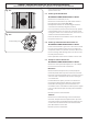
3.3 To Change the Ignition Generator
DISCONNECT FROM THE ELECTRICITY SUPPLY.
Pull the cooker forwards to gain access to the cover box at
the rear of the cooker. Remove the screws securing the cover
and lift clear. Pull o all the leads to the generator noting their
positions. Slacken the 2 screws holding generator to cooker
and remove the generator.
Fit the new generator to the cooker and replace the leads.
Refer to the wiring diagram and reassemble in reverse order.
Check ignition performance.
4 Grill
4.1 To Replace the Grill Controller
DISCONNECT FROM THE ELECTRICITY SUPPLY.
Remove the control panel and hotplate (see 1.1 & 2.1).
Disconnect the wiring from controller. Remove the 2screws
holding the controller to the mounting panel.
Fit the new controller and reassemble in the reverse order.
Check for correct operation.
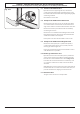
4.2 To Replace the Grill Element
DISCONNECT FROM THE ELECTRICITY SUPPLY.
Remove the grill pan from the grill chamber. From inside
the grill compartment, undo the 2 screws and washers and
remove the enamelled front shield from the grill roof. Remove
2 screws and washers securing the grill element front support.
Remove the screws from the grill elements.
Carefully lift the elements out and disconnect the leads from
the element terminals, noting their position.
If it is not possible to disconnect the leads in this way, pull
cooker forwards to gain access to the rear.
Remove the screws securing the electric cover to the back
sheet, and then remove cover and disconnect the terminals
from the rear.
Fit the new elements and reassemble in reverse order. Check
the operation of the grill.
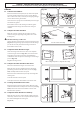
5 Ovens
5.1 To Remove the Oven Inner Back
Main Oven
Open the main oven door. Remove the 4 screws and washers
securing the inner back to the back of the oven (Fig. 10.3).
Carefully lift away the inner back.
Reassemble in reverse order, making sure that you fully
tighten the 4 screws and washers.
Tall Oven
Open the tall oven door and remove the 2 screws and washers
securing the inner back to the back of the oven. Carefully lift
away the inner back.
Reassemble in reverse order.
Check the door for correct operation.
5.2 To Change the Oven Fan
DISCONNECT FROM THE ELECTRICITY SUPPLY.
Pull the cooker forward to gain access to the rear. Remove
the screws securing the electric cover to the back sheet and
remove the cover. Disconnect the 3terminals connected to
the fan, noting their position.
Remove the oven inner back (see 5.1). Hold the fan blade and
remove the centre nut (left-hand thread), 2brass washers, fan
blade and circlip. Unscrew the fan retaining nuts and washers
(3 o each) and lift the fan away from the rear of the cooker.