USER GUIDE & INSTALLATION INSTRUCTIONS Nexus 90 Dual Fuel Australia U110621-02
SLOW BAKED LEG OF LAMB METHOD 1. reheat the oven to 220 °C (for a conventional oven), 200 °C (for a P fan oven) or gas mark 7. 2. Pull the small sprigs off the rosemary branches and set aside with the garlic. 3. sing the tip of a paring knife, make up to 20 well-spaced cuts into U the flesh of the lamb, about 2.5 cm inch deep. Divide the rosemary sprigs, garlic and anchovies and push down into the cuts. Place the leg on a large roasting tin and pour over the oil, massaging it all over the joint.
Contents 1. 2. 3 Before You Start... 1 6. Troubleshooting 21 Personal Safety 1 Electrical Connection Safety 2 7.
ii
1. Before You Start... Personal Safety Your cooker should give you many years of trouble-free cooking if installed and operated correctly. It is important that you read this section before you start. This appliance is for cooking purposes only. It must not be used for other purposes, for example heating a room. Using it for any other purpose could invalidate any warranty or liability claim. Besides invalidating claims this wastes fuel and may overheat the control knobs.
Electrical Connection Safety Gas Connection Safety A qualified service engineer should service the cooker and only approved spare parts should be used. • This cooker is a Class 2 Subclass 1 appliance. • This appliance can be converted for use on another gas. • Before installation, make sure that the cooker is suitable for your gas type and supply voltage. See the data badge. • DO NOT use reconditioned or unauthorised gas controls. • Disconnect from the electricity and gas supply before servicing.
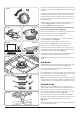
Maintenance Oven Care • When the oven is not in use and before attempting to clean the cooker always be certain that the control knobs are in the OFF position. • Use oven gloves to protect your hand from potential burns. • Cooking high moisture content foods can create a ‘steam burst’ when the oven door is opened (Fig. 1.1). When opening the oven, stand well back and allow any steam to disperse. • The inside door face is constructed with toughened safety glass.
Hob Care Cleaning • NEVER allow anyone to climb or stand on the hob. • DO NOT use the hob surface as a cutting board. • DO NOT leave utensils, foodstuffs or combustible items on the hob when it is not in use (e.g. tea towels, frying pans containing oil). • DO NOT place plastic or aluminium foil, or plastic containers on the hob. • Always turn the control to the OFF position before removing a pan. • Avoid heating an empty pan. Doing so may damage both the hob and pan.
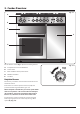
2. Cooker Overview Fig. 2.1 A B C E D The 90 dual fuel cooker (Fig. 2.1) has the following features: A. 4 hotplate burners and a Wok Burner B. Control Panel C. Glide-out Grill™ with 4 position Trivet D. Multifunction Oven E. Fan Oven Fig. 2.2 Hotplate Burners The labels by each of the control knobs indicates which area that knob controls. Each burner has a Flame Supervision Device (FSD) that prevents the flow of gas if the flame goes out.
The igniter should spark and light the gas. Continue to press in the knob to let the gas through to the burner for about ten seconds. Fig. 2.3 If and when you let go of the control knob or the burner goes out, then the FSD has not been bypassed. Turn the control knob to the OFF position and wait for one minute before you try again, this time making sure to hold in the control knob for slightly longer. Adjust the flame height to suit by turning the knob counterclockwise (Fig. 2.3).
The Griddle Fig. 2.11 The griddle fits the left-hand pan support, front to back (Fig. 2.11). It is designed for cooking food on directly. DO NOT use pans of any kind on it. The griddle surface is non-stick and metal cooking utensils (e.g. spatulas) will damage the surface. Use heat resistant plastic or wooden utensils. DO NOT put it crossways – it will not fit properly and nn will be unstable (Fig. 2.12). DO NOT put it on any other burner – it is not nn designed to fit in any of the other pan supports.
The Glide-out Grill™ Fig. 2.15 Open the door and pull the grill pan carriage forward using the handle (Fig. 2.15). The grill has two elements that allow either the whole area of the pan to be heated or just the right-hand half. Adjust the heat to suit by turning the control knob. To heat the whole grill, turn the knob clockwise (Fig. 2.16). To heat the right-hand half, turn the knob counter-clockwise. The neon indicator light by the grill control will come on.
The Ovens The clock must be set to the time of day before the left hand oven will work. See the following section on ‘The Clock’ for instructions on setting the time of day. References to ‘left-hand’ and ‘right-hand’ ovens apply as viewed from the front of the appliance. The left-hand oven is a multifunction oven, while the righthand oven is a fan oven.
Fan Assisted Oven This function operates the fan, circulating air heated by the elements at the top and the base of the oven. The combination of fan and conventional cooking (top and base heat) makes this function ideal for cooking large items that need thorough cooking, such as a large meat roast. Multifunction Oven Functions Defrost This function operates the fan to circulate cold air only. Make sure the temperature control is at 0°C and that no heat is applied.
Operating the Ovens Fig. 2.18 Operating the Multifunction Oven The multifunction oven has two controls: a function selector and a temperature setting knob (Fig. 2.18). Turn the function selector control to a cooking function. Turn the oven temperature knob to the temperature required (Fig. 2.18). The oven heating light will glow until the oven has reached the temperature you selected (Fig. 2.20). It will then cycle on and off during cooking as the oven maintains the selected temperature.
Using the Clock Fig. 2.21 You can use the clock to turn the left-hand oven on and off. Note: When using the timer functions, first set the clock as required before setting the oven temperature. The oven can be switched on when the cook symbol [ ] is displayed. Setting the Clock 1. The LCD clock is shown in (Fig. 2.21). Once the cooker is connected and switched on, the display flashes (00.00 ) and the time starts from (00.00 ). 2.
To Start and Then Stop the Left-hand Oven Set the left-hand oven to automatically start and stop using a combination of the ‘cook period’ and ‘stop time’. Fig. 2.27 You cannot set a start time directly – this is set automatically by a combination of the ‘cook period’ and ‘stop time’. ArtNo.306-0001 - 3-button clock 1. Press the mode [M] button until the display flashes (dur) (Fig. 2.27). Then set the ‘cook period’ using the [+] or [-] buttons. 2.
Accessories Fig. 2.32 Shelf guard Oven Shelves – Left-hand (Main) Oven The oven shelves (Fig. 2.32) are retained when pulled forward but can be easily removed and refitted. Pull the shelf forward until the back of the shelf is stopped by the shelf stop bumps in the oven sides (Fig. 2.33). Front Lift up the front of the shelf so the back of the shelf will pass under the shelf stop and then pull the shelf forward (Fig. 2.34). Fig. 2.33 Fig. 2.34 ArtNo.320-0011 Removing the shelf 1 Fig. 2.
4 Cooking Tips Tips on Cooking with the Timer General Oven Tips If you want to cook more than one dish, choose dishes that require approximately the same cooking time. However, dishes can be ‘slowed down’ slightly by using small containers and covering them with aluminium foil, or ‘speeded up’ slightly by cooking smaller quantities or placing them in larger containers. The wire shelves should always be pushed firmly to the back of the oven.
5. Cooking Table DocNo.031-0004 - Cooking table - electric & fan single cavity The oven control settings and cooking times given in the table below are intended to be used AS A GUIDE ONLY. Individual tastes may require the temperature to be altered to provide a preferred result. Food is cooked at lower temperature in a fan oven than in a conventional oven. When using recipes, reduce the fan oven temperature by 10 °C and the cooking time by 5-10 minutes.
ArtNo.045-0004 - Cleaning - 90 induction - tpl glzd dr & GO grill 5. Cleaning Your Cooker Essential Information Fig. 5.1 A Isolate the electricity supply before carrying out any thorough cleaning. Allow the cooker to cool. C NEVER use paint solvents, washing soda, caustic nn cleaners, biological powders, bleach, chlorine based B bleach cleaners, coarse abrasives or salt. DO NOT mix different cleaning products – they may nn react together with hazardous results.
Grills Fig. 5.5 The grill pan and trivet should be washed in hot soapy water. Alternatively, the grill pan can be washed in a dishwasher. After grilling meats or any foods that soil, leave to soak for a few minutes immediately after use. Stubborn particles may be removed from the trivet using a nylon brush. Before you remove any of the grill parts for cleaning, make sure that they are cool, or use oven gloves.
Glass Fronted Door Panels Fig. 5.10 The oven door front panels can be taken off so that the glass panels can be cleaned. Move the cooker forward to gain access to the sides (see the ‘Moving the Cooker’ section under ‘Installation’). Open the oven door slightly and remove the front panel fixing screws from the door sides, two each side (Fig. 5.10). Carefully lift off the outer door panel. The inside face of the glass panels can now be cleaned – take care not to disturb or wet the door insulation. ArtNo.
Cleaning Table Cleaners listed (Table 5.1) are available from supermarkets or electrical retailers as stated. For enamelled surfaces use a cleaner that is approved for use on vitreous enamel. Regular cleaning is recommended. For easier cleaning, wipe up any spillages immediately. Hotplate Part Finish Recommended Cleaning Method Hob top (including burner heads and caps) Enamel, stainless steel, aluminium Hot soapy water, soft cloth. Any stubborn stains remove gently with a nylon scourer.
6. Troubleshooting Food is cooking too slowly, too quickly, or burning Cooking times may differ from your previous oven. Hotplate/Cooktop ignition or hotplate burners faulty Is the power on? If not, there maybe something wrong with the power supply. Check that you are using the recommended temperatures and shelf positions – see the oven cooking guide. The oven control settings and cooking times are intended to be used only as a guide.
Fig. 6.1 ArtNo.324-0005 Oven light bulb Oven light is not working The bulb has probably burnt out. You can buy a replacement bulb (which is not covered under the warranty) from a good electrical shop. Ask for a 15 W – 230 V lamp, FOR OVENS. It must be a special bulb, heat resistant to 300 °C (Fig. 6.1). Turn off the power at the circuit breaker. Before removing the existing bulb, turn off the power supply and make sure that the oven is cool. Open the oven door and remove the oven shelves. Fig. 6.
INSTALLATION Check the appliance is electrically safe and gas sound when you have finished. 7. Installation Service and Spares Firstly, please complete the appliance details below and keep them safe for future reference – this information will enable us to accurately identify the particular appliance and help us to help you. Filling this in now will save time and inconvenience if you later have a problem with the appliance. It may also be of benefit to keep your purchase receipt with this leaflet.
INSTALLATION Check the appliance is electrically safe and gas sound when you have finished. Safety Requirements and Regulations Provision of Ventilation You must be aware of the following safety requirements & regulations. This appliance is not connected to a combustion products evacuation device. Particular attention shall be given to the relevant requirements regarding ventilation.
INSTALLATION Check the appliance is electrically safe and gas sound when you have finished. 3 pan supports ArtNo.000-0001 90 Pan supports You will need the following equipment to complete the cooker installation satisfactorily: • * Restraining chain and hook: If the cooker is to be supplied with gas through a flexible hose, a restraining chain and hook MUST be fitted. These are not supplied with the cooker but are available at most builders’ merchants.
INSTALLATION Check the appliance is electrically safe when you have finished. Positioning the Cooker Fig. 7-1 E Hob The diagram (Fig. 8.1) shows the minimum recommended distance from the cooker to nearby surfaces as given in AS/NZS 5601. D B * *Any splashback must be fitted in accordance with the manufacturers instructions. Allowance should be made for the additional height of the flue trim, which is fitted to the cooker hob. A C 1.
INSTALLATION Check the appliance is electrically safe and gas sound when you have finished. Moving the Cooker Fig. 7.1 On no account try and move the cooker while it is plugged into the electricity supply. nn The cooker is very heavy, so take extra care. nn We recommend that two people manoeuvre the cooker. Make sure that the floor covering is firmly fixed, or removed, to prevent it being disturbed when moving the cooker around.
INSTALLATION Check the appliance is electrically safe and gas sound when you have finished. Fitting the Stability Bracket or Chain Fig. 7.5 Unless otherwise stated, a cooker using a flexible gas connector must be secured with a suitable stability device. Stability chain Suitable stability devices are shown in Fig. 7.5, Fig. 7.6, Fig. 7.7 and Fig. 7.8. If you are using a stability chain (Fig. 7.5) then the chain should be kept as short as is practicable and fixed firmly to the rear of the cooker.
INSTALLATION Check the appliance is electrically safe and gas sound when you have finished. Gas Connection Fig. 7.1 This must be in accordance with the relevant standards. 675 The gas supply needs to terminate with a down-facing threaded fitting ½” connection. The inlet connector is located just below the hotplate level at the rear of the cooker. Gas inlet 315 Because the height of the cooker can be adjusted and each connection is different, it is difficult to give precise dimensions.
INSTALLATION Check the appliance is electrically safe and gas sound when you have finished. Electrical Connection Fig. 7.1 This appliance must be installed by a qualified electrician to comply with with current AS/NZS 3000 Wiring Rules and regulations in force. Make sure that the mains characteristics (voltage, nominal, power, etc.) match the ratings indicated on the data plate affixed to the cooker. ArtNo.
INSTALLATION Check the appliance is electrically safe and gas sound when you have finished. Fixed Wiring Fig. 7.3 Disconnect from the mains supply. nn For connection to fixed wiring, i.e. flexible conduit, Remove the electrical terminal cover on the back panel (Fig. 7.3). Remove the M4 screw securing the reducer plates to the conduit box (Fig. 7.4). Fit the conduit box to the cooker using the two M5 screw fittings located at the top of the box and the M4 screw (Fig. 7.5).
INSTALLATION Check the appliance is electrically safe when you have finished. 8. Final Fitting Final Checks Fig. 8-1 Hob Check Check each cooking zone in turn. Be sure to use pans of the correct size and material. Grill Check Turn on the grill control and check that the grill heats up. Oven Check x 2 positions Set the clock as described earlier, and then turn on the ovens. Check the oven fans start to turn and that the ovens heat up. ArtNo.
WARNING – SERVICING TO BE CARRIED OUT ONLY BY AN AUTHORISED PERSON Disconnect from electricity and gas before servicing. Check appliance is safe when you have finished. 9. Conversion to LP Gas Conversion from Natural Gas (1.0 kPa) to LPG X Propane (2.54 kPa) Fig. 9.1 A suitably competent person must perform the nn conversion. After conversion the installation must comply with the relevant regulations and also the local electricity supply company requirements.
WARNING – SERVICING TO BE CARRIED OUT ONLY BY AN AUTHORISED PERSON Disconnect from electricity and gas before servicing. Check appliance is safe when you have finished. Set the Governor Fig. 9.4 Unscrew the governor’s brass top. In the base of the brass top is a plastic snap-in converter device (Fig. 9.4). To convert the governor, snap the device out of the top and refit it the other way round. The snap-in converter device is marked to show the gas for which it is set (Fig. 9.5). ArtNo.
WARNING – SERVICING TO BE CARRIED OUT ONLY BY AN AUTHORISED PERSON Disconnect from electricity before servicing. Check appliance is safe when you have finished. 10. Servicing BEFORE SERVICING ANY GAS CARRYING nn COMPONENTS TURN OFF THE GAS SUPPLY Fig. 10.1 A Check the appliance is gas sound after completion nn of service. When checking for gas leaks DO NOT use washing up liquid – this can corrode. Use a product specifically manufactured for leak detection.
WARNING – SERVICING TO BE CARRIED OUT ONLY BY AN AUTHORISED PERSON Disconnect from electricity before servicing. Check appliance is safe when you have finished. 2.3 To Change a Hotplate Burner Injector 2 Hotplate Remove the burner cap and head. Remove the old injector. BEFORE SERVICING ANY GAS CARRYING nn COMPONENTS, TURN OFF THE GAS SUPPLY. Fit the new injector. Reassemble in reverse order. Check the appliance is gas sound. 2.1 To Remove the Hotplate 2.
WARNING – SERVICING TO BE CARRIED OUT ONLY BY AN AUTHORISED PERSON Disconnect from electricity before servicing. Check appliance is safe when you have finished. 3 Controls 4 Grill 3.1. To Replace the Ignition or Light Switch 4.1 To Replace the Grill Controller DISCONNECT FROM THE ELECTRICITY SUPPLY. DISCONNECT FROM THE ELECTRICITY SUPPLY. Remove the control panel (see 1.1). Remove the control panel and hotplate (see 1.1 & 2.1). Disconnect the wiring from controller.
WARNING – SERVICING TO BE CARRIED OUT ONLY BY AN AUTHORISED PERSON Disconnect from electricity before servicing. Check appliance is safe when you have finished. Fit the new fan and reassemble in reverse order. Check the operation of the oven. Fig. 10.3 5.3 To Change the Oven Element DISCONNECT FROM THE ELECTRICITY SUPPLY. Remove the oven inner back (see 5.1). Remove the 2 screws from the top of the element and the 1 from the bottom of the element (Fig. 10.4).
WARNING – SERVICING TO BE CARRIED OUT ONLY BY AN AUTHORISED PERSON Disconnect from electricity before servicing. Check appliance is safe when you have finished. 6 Doors Fig. 10.5 6.1 To Remove the Grill Door Fig. 10.6 Remove the left-hand side panel (see 1.2). Remove the plinth (4 screws) and the central vertical cover (5 screws). Remove the 2 countersunk screws (1 each side) securing the grill hinge arms to the front of the grill chamber. 2 1 Note: The arms are spring tensioned.
WARNING – SERVICING TO BE CARRIED OUT ONLY BY AN AUTHORISED PERSON Disconnect from electricity before servicing. Check appliance is safe when you have finished. 6.7 To Remove the Tall Oven Door Fig. 10.12 Open the oven door. Supporting the door, remove the 2 screws securing the upper hinge and packing to the cooker front. Remove the door from the lower hinge by lifting slightly and moving outwards. Reassemble in reverse order. 6.
11.
12. Technical Data THE COOKER IS CATEGORY: CatII2H3+. It is supplied set for group H natural gas. A conversion kit from NG to LP is available for the cooker. INSTALLER: Please leave these instructions with the user. DATA BADGE LOCATION: Cooker back, serial number repeater badge below oven door opening. COUNTRY OF DESTINATION: Australia. Pressures Gas (Rp ½ at rear right-hand side) Electric Supply Pressure at the inlet to appliance regulator Natural Gas 1.13 kPa Propane 2.
Hotplate Efficiency Brand Falcon Model Identification Nexus Size 90 Type Dual Fuel Type of Hob GAS Number of gas burners 5 Auxiliary / Small Burner (EE gas burner) - Semi Rapide / Medium Burner (EE gas burner) 58% Semi Rapide / Medium Burner (EE gas burner) 58% Rapide / Large Burner (EE gas burner) 56% Rapide / Large Burner (EE gas burner) - Wok (EE gas burner) 53% Wok (EE gas burner) - Hotplate EE gas hob (*) 56% Information marked thus (*) is not required with mixed fuel hobs
Oven Data Brand Falcon Model identification Nexus Type of oven Electric Mass kg 112 Number of cavities 2 Left-hand Efficiency Fuel type Electric Cavity type Multifunction Power - conventional 2.2 Power - forced air convection 2.5 Volume Litres 73 Energy consumption (electricity) - conventional kWh / cycle 1.08 Energy consumption (electricity) - forced air convection kWh / cycle 0.91 Energy efficiency index - conventional 126.
Note 37
Note 38
Note 39
Clarence Street, Royal Leamington Spa, Warwickshire, CV31 2AD, England. Tel: +44 (0) 1926 457400 Fax: +44 (0) 1926 450526 E-mail: consumers@falconappliances.co.