
User's Manual
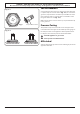
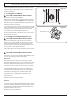
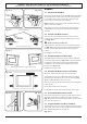
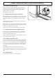
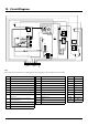
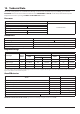
Table Of Contents
- 1. Before You Start...
- 2. Cooker Overview
- 3. Using the Glide-out Grill™
- 4. 3 button clock
- 5. Cooking Table
- 6. Cleaning your cooker
- 7. Troubleshooting
- 8. Service and Spares
- 9. Installation
- Safety Requirements and Regulations
- Provision of Ventilation
- Location of Cooker
- Conversion
- Positioning the Cooker
- Moving the Cooker
- Lowering the Two Rear Rollers
- Completing the Move
- Levelling
- Repositioning the Cooker Following Connection
- Gas Connection
- Natural Gas
- Propane
- Pressure Testing
- Electrical Connection
- Fixed Wiring
- Final Fitting and Checks
- 10. Conversion to LP Gas
- 11. Servicing
- 12. Circuit Diagram
- 13. Technical Data

WARNING – SERVICING TO BE CARRIED OUT ONLY BY AN AUTHORISED PERSON
Disconnect from electricity before servicing. Check appliance is safe when you have nished.
37
Reassemble in reverse order ensuring that the leads are
reconnected. Take care not to damage the ignition electrodes
of the burners.
It is important that the rear earthing leads are replaced when
the xing screws are retted as they from part of the cooker
earthing.
Check for correct burner operation.
2.2 To Replace the Hotplate Control Taps
n
DISCONNECT FROM THE ELECTRICITY SUPPLY.
n
BEFORE SERVICING ANY GAS CARRYING
COMPONENTS, TURN OFF THE GAS SUPPLY.
Remove the control panel and hotplate (see 1.1 & 2.1).
Unplug the FSD lead from the rear of the tap. Undo the
compression tting at the rear of the tap and remove the
xings that secure the tap to the gas rail. Disconnect the
ignition switch wiring.
Remove the tap. Remove and discard the gasket seal. Fit
the new gasket seal to the replacement tap. Reassemble in
reverse order. Check that the appliance is gas sound. Verify
the hotplate ignition.
2.3 To Change a Hotplate Burner Injector
Remove the burner cap and head. Remove the old injector.
Fit the new injector. Reassemble in reverse order. Check the
appliance is gas sound.
2.4 To Replace a Hotplate Burner Electrode
n
DISCONNECT FROM THE ELECTRICITY SUPPLY.
Lift o pan supports and remove the burner cap. Remove the
screw holding the electrode. Pull the electrode vertically up
suciently to grip the lead between thumb and forenger.
Pull o the electrode, but keep hold of the lead. Fit the new
electrode to the lead. Fix the electrode in the burner with
screw. Replace the burner cap.
Check the burner ignition. Replace the pan supports.
2.5 To Replace a Hotplate Burner
n
DISCONNECT FROM THE ELECTRICITY SUPPLY.
Remove the hotplate tray (see 2.1). The burners (except
the right-hand wok burner) are mounted on support struts.
For these burners, disconnect the burner feed pipes at the
burner. Remove the screws at the front and rear holding the
support struts. Lift the strut and burners clear. The burners
are xed to the support struts with 2 screws. Remove the
appropriate burner and t the new one.
Reassemble in reverse order. Check that the burner operation
is satisfactory.
Right-hand Wok Burner
Disconnect the burner feed pipe at the burner.
Fit the new one and reassemble in reverse order. Check that
the burner operation is satisfactory.
2.6 To Change a Hotplate Burner Thermocouple
n
DISCONNECT FROM THE ELECTRICITY SUPPLY.
Remove the control panel and hotplate (see 1.1 & 2.1).
Unplug the FSD lead from the rear of the tap.
The thermocouple sits in a hole that has a slot at one side.
Ensure that the thermocouple is cool. Turn the thermocouple
so that the earth lead (no sleeve) is in line with the slot. Lift
the thermocouple clear of the hole.
Reassemble in reverse order.
3 Controls
3.1. To Replace the Ignition or Light Switch
n
DISCONNECT FROM THE ELECTRICITY SUPPLY.
Remove the control panel (see 1.1).
Note: The old switch may be destroyed during removal.
Remove the old switch from its bezel by gripping the switch
body behind the control panel and twisting sharply. Remove
the switch bezel by folding back the locking wings and
pushing forward.
To t the new bezel to the control panel: rst line up the
raised key on its body with the cut-out in the control panel
and push it in from the front.
Assemble the new switch to the bezel by lining up the key
sections and pushing home. Fit the new button by pushing in
from the front.
Replace the control panel in the reverse order and test for
correct operation.
3.2 To Replace the Clock
n
DISCONNECT FROM THE ELECTRICITY SUPPLY.
Remove the control panel (see 1.1). Pull o the timer control
buttons.
Undo the timer xing screws and remove the timer/mounting
bracket assembly from the control panel.
Remove the timer from its mounting bracket by depressing
the plastic lugs on the timer case, and at the same time
pulling the unit forward.
Reassemble in reverse order. When replacing the leads, refer
to the wiring diagram. Check the operation of the timer.
3.3 To Change the Ignition Generator
n
DISCONNECT FROM THE ELECTRICITY SUPPLY.
Pull the cooker forwards to gain access to the cover box at the
rear of the cooker. Remove the screws securing the cover and
lift clear. Pull o all the leads to the generator noting their
positions. Slacken the 2 screws holding generator to cooker
and remove the generator.
Fit the new generator to the cooker and replace the leads.
Refer to the wiring diagram and reassemble in reverse order.
Check ignition performance.