
User's Manual
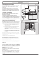
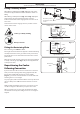
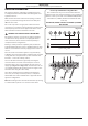
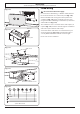
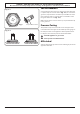
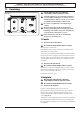
Table Of Contents
- 1. Before You Start...
- 2. Cooker Overview
- 3. Using the Glide-out Grill™
- 4. 3 button clock
- 5. Cooking Table
- 6. Cleaning your cooker
- 7. Troubleshooting
- 8. Service and Spares
- 9. Installation
- Safety Requirements and Regulations
- Provision of Ventilation
- Location of Cooker
- Conversion
- Positioning the Cooker
- Moving the Cooker
- Lowering the Two Rear Rollers
- Completing the Move
- Levelling
- Repositioning the Cooker Following Connection
- Gas Connection
- Natural Gas
- Propane
- Pressure Testing
- Electrical Connection
- Fixed Wiring
- Final Fitting and Checks
- 10. Conversion to LP Gas
- 11. Servicing
- 12. Circuit Diagram
- 13. Technical Data

INSTALLATION
Check the appliance is gas sound when you have nished.
27
ArtNo.110-0023 - 110 - cooker clearances (AUS)
Hob
Trivet
Horizontal combustible surface
B
C
D
E
A
*
or
ArtNo.090-0025 - 90 classic (gas) door clearances
130 mm
Positioning the Cooker
The diagram (Fig. 9.1) shows the minimum recommended
distance from the cooker to nearby surfaces as given in
AS/NZS 5601.
*Any splashback must be tted in accordance with the
manufacturers instructions. Allowance should be made for
the additional height of the ue trim, which is tted to the
cooker hob.
1. Overhead - Measurement A
The minimum height of any surface above the cooker is
650 mm above the hotplate.
Cookerhoods and exhaust fans shall be installed in
accordance with the manufacturer’s instructions. However, in
no case shall the clearance between the highest part of the
hob of the cooking appliance and a cookerhood be less than
650 mm or, for an overhead exhaust fan, 750 mm.
2. Side Clearances - Measurements B & C
Where B, measured from the periphery of the nearest burner
to any vertical combustible surface is less than 200 mm, the
surface shall be protected by one of the following methods:
a. Fixing ceramic tiles with a minimum thickness of
5 mm to the surface.
b. Fixing toughened glass with a minimum thickness
of 5 mm to the surface, provided the glass is
approved by the manufacturer to be suitable for the
application.
c. Attaching re resistant material to the surface and
covering with sheet metal with a minimum thickness
of 0.4 mm.
Protection should be to a height C of not less than 150 mm
above the hob for the full dimension (width or depth) of the
cooking surface area.
3. Side Clearances - Measurement D & E
Where D, the distance from the periphery of the nearest
burner to a horizontal combustible surface is less than
200 mm, then E shall be 10 mm or more, or the horizontal
surface shall be above the trivet.
If the horizontal surface is above the trivet, then any vertical
combustible surface needs to be protected in accordance
with B above.
If the cooker is near a corner of the kitchen, a clearance if
130 mm is required to allow the oven doors to open (Fig. 9.2).
The actual opening of the doors is slightly less, but this allows
for some protection of your hand as you open the door.
DO NOT place the cooker on a base.
For safety reasons, curtains,must not be tted immediately
behind the cooker.
We recommend a gap of 910 mm between units to allow for
moving the cooker. Do not box the cooker in – it must still
be possible to move the cooker in and out for cleaning and
servicing.
Fig. 9.1
Fig. 9.2