
User's Manual
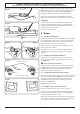
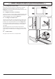
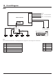
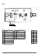
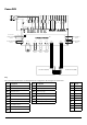
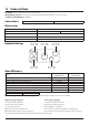

Table Of Contents
- 1. Before You Start...
- 2. Cooker Overview
- 3. Using the Glide-out Grill™
- 4. The Multifunction Oven
- 5. The Steam Cavity
- 6. Cleaning Your Cooker
- 7. Troubleshooting
- 8. Installation
- Dear Installer
- Safety Requirements and Regulations
- Provision of Ventilation
- Location of Cooker
- Positioning the Cooker
- Moving the Cooker
- Lowering the Two Rear Rollers
- Completing the Move
- Fitting the Stability Bracket
- Repositioning the Cooker Following Connection
- Levelling
- Electrical Connection
- Connection in New Zealand
- Fixed Wiring
- Final Checks
- Final Fitting
- Customer Care
- 9. Servicing
- 10. Circuit Diagram
- 11. Technical Data
47
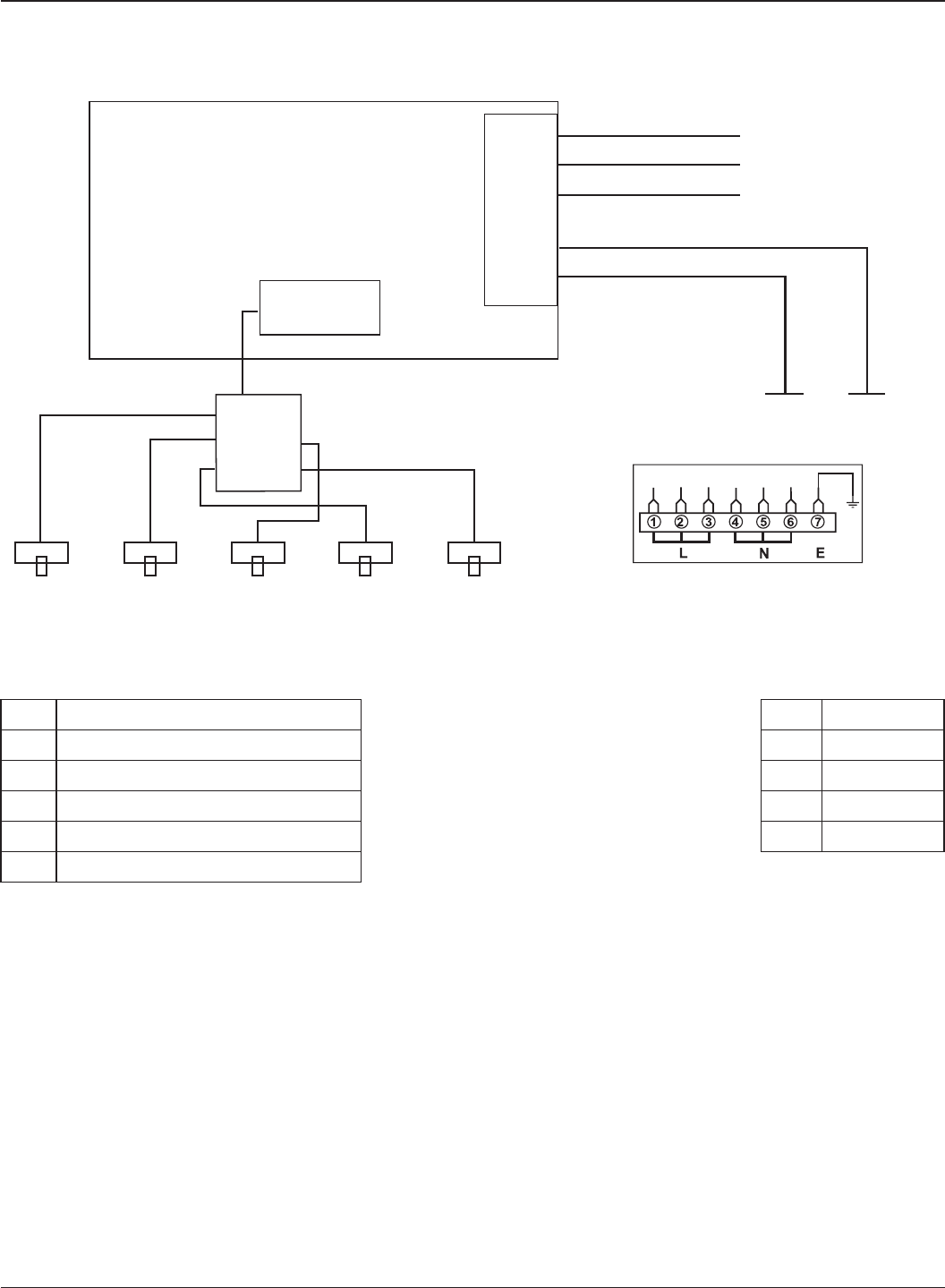
10. Circuit Diagram
Hob
12
53
4
E
5
4
3
2
1
INTERFACE
BOARD
1
2
5
4
3
INDUCTION UNIT
HOB
DISPLAY
Earth
N(6)
N(4)
L(2) L(3)
On Terminal Bloc
k
On Terminal Block
On Terminal Block
w/br
w/br
w/br
w/br
w/br
Key
The connections shown in the circuit diagram are for single-phase. The ratings are for 230 V 50 Hz.
Code Description
1 Left-hand front element
2 Left-hand rear element
3 Right-hand rear element
4 Right-hand front element
5 Centre element
Code Colour
b
Blue
br
Brown
g/y
Green/yellow
w/br
White/brown