
User's Manual
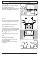
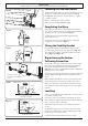
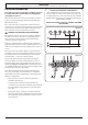
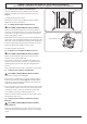
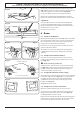
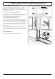
Table Of Contents
- 1. Before You Start...
- 2. Cooker Overview
- 3. Using the Glide-out Grill™
- 4. The Multifunction Oven
- 5. The Steam Cavity
- 6. Cleaning Your Cooker
- 7. Troubleshooting
- 8. Installation
- Dear Installer
- Safety Requirements and Regulations
- Provision of Ventilation
- Location of Cooker
- Positioning the Cooker
- Moving the Cooker
- Lowering the Two Rear Rollers
- Completing the Move
- Fitting the Stability Bracket
- Repositioning the Cooker Following Connection
- Levelling
- Electrical Connection
- Connection in New Zealand
- Fixed Wiring
- Final Checks
- Final Fitting
- Customer Care
- 9. Servicing
- 10. Circuit Diagram
- 11. Technical Data

WARNING – SERVICING TO BE CARRIED OUT ONLY BY AN AUTHORISED PERSON
Disconnect from electricity before servicing. Check appliance is safe when you have nished.
43
n
Disconnect from the electricity supply before
servicing, particularly before removing any of the
following: control panel, side panels, ceramic hob or
any electrical components or covers.
n
Before electrical reconnection, check that the
appliance is electrically safe.
1 Panels
1.1 To Remove the Control Panel
n
DISCONNECT FROM THE ELECTRICITY SUPPLY.
Pull o all the control knobs and remove the xing screws
underneath the control panel.
The control panel will drop down slightly. It is held at the top
by two holes in the top edge, one at each end, that locate on
the tags on the inner panel. Lift the control panel clear of the
tags and pull forwards, taking care not to damage or strain
the wiring.
1.2 To Remove the Side Panels
n
DISCONNECT FROM THE ELECTRICITY SUPPLY.
Remove the control panel (see 1.1). Pull the cooker forward.
Remove the 4 retaining screws for each panel (1 at the front
base, 1 on the top and 2 at the rear).
Reassemble in the reverse order.
2 Hotplate
n
DISCONNECT FROM THE ELECTRICITY SUPPLY.
2.1 To Lift up the Induction Hob
Remove the rubber plugs and retaining screws (1 each side)
at the top front of the side panels.
Lift up the induction hob at the front and prop into position
with a non-metallic prop.
CAUTION: The induction hob material is much more sensitive
to scratches on the underside than the top.
Take care not to touch or scratch the underside of the ceramic
as this will weaken the material and cause the top to shatter.
3 Controls
3.1. To Replace the Light Switch
n
DISCONNECT FROM THE ELECTRICITY SUPPLY.
Remove the control panel (see 1.1).
Note: The old switch may be destroyed during removal.
Remove the old switch from its bezel by gripping the switch
body behind the control panel and twisting sharply. Remove
the switch bezel by folding back the locking wings and
pushing forward. To t the new bezel to the control panel:
rst line up the raised key on its body with the cut-out in the
control panel and push it in from the front.
9. Servicing
Assemble the new switch to the bezel by lining up the key
sections and pushing home. Fit the new button by pushing in
from the front.
Replace the control panel in the reverse order and test for
correct operation.
4 Grill
4.1 To Replace the Grill Controller
n
DISCONNECT FROM THE ELECTRICITY SUPPLY.
Remove the control panel and hotplate (see 1.1 & 2.1).
Disconnect the wiring from controller. Remove the 2screws
holding the controller to the mounting panel.
Fit the new controller and reassemble in the reverse order.
Check for correct operation.
4.2 To Replace the Grill Element
n
DISCONNECT FROM THE ELECTRICITY SUPPLY.
Remove the grill pan from the grill chamber. From inside
the grill compartment, undo the 2 screws and washers
and remove the enamelled front shield from the grill roof.
Remove 2 screws and washers securing the grill element front
support. Remove the screws from the grill elements.
Carefully lift the elements out and disconnect the leads from
the element terminals, noting their position.
If it is not possible to disconnect the leads in this way, pull
cooker forwards to gain access to the rear.
Remove the screws securing the electric cover to the back
sheet, and then remove cover and disconnect the terminals
from the rear.
Fit the new elements and reassemble in reverse order. Check
the operation of the grill.
5 Ovens
5.1 To Replace the Left-hand Oven Thermostat
n
DISCONNECT FROM THE ELECTRICITY SUPPLY.
Remove the control panel and hotplate (see 1.1 & 2.1). Open
the oven door and remove the oven furniture.
Pull the cooker forward to gain access to the cover box at the
rear of the cooker. Remove the 4 screws securing the cover
and lift clear.
Feed the thermostat capillary out of the oven. Disconnect
the wiring from the thermostat. Remove 2screws holding
thermostat to mounting panel. Fit new thermostat and
reassemble in the reverse order. Make sure that the phial is
clipped to the oven back with the phial centrally positioned
between the clips.
Check the operation of the thermostat.