USER GUIDE & INSTALLATION INSTRUCTIONS Nexus 110 Induction Australia
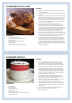
SLOW BAKED LEG OF LAMB METHOD 1. reheat the oven to 220 °C (for a conventional oven), 200 °C (for a P fan oven) or gas mark 7. 2. Pull the small sprigs off the rosemary branches and set aside with the garlic. 3. sing the tip of a paring knife, make up to 20 well-spaced cuts into U the flesh of the lamb, about 2.5 cm inch deep. Divide the rosemary sprigs, garlic and anchovies and push down into the cuts. Place the leg on a large roasting tin and pour over the oil, massaging it all over the joint.
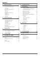
Contents 1. 2. 3. Before You Start... 1 6. Troubleshooting 25 Personal Safety 1 Electrical Connection Safety 2 7.
ii
1. Before You Start... Personal Safety Your cooker should give you many years of trouble-free cooking if installed and operated correctly. It is important that you read this section before you start. This appliance is for cooking purposes only. It must not be used for other purposes, for example heating a room. Using it for any other purpose could invalidate any warranty or liability claim. Besides invalidating claims this wastes fuel and may overheat the control knobs.
Electrical Connection Safety Maintenance A qualified service engineer should service the cooker and only approved spare parts should be used. • It is recommended that this appliance is serviced annually. • DO NOT use cooking vessels on the hotplate that overlap the edges. • Unless specified otherwise in this guide, always allow the cooker to cool and then switch it off at the mains before cleaning or carrying out any maintenance work.
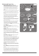
Induction and Ceramic Care • Important information for pacemaker and implanted insulin pump users: The functions of this hob comply with the applicable European standards on electromagnetic interference. If you are fitted with a pacemaker or implanted insulin pump and are concerned please consult your doctor for medical advice. • When the hob is in use keep magnetic items away, such as credit and debit cards, floppy disk, calculators, etc. • Take care when touching the marked cooking areas of the hob.
• The ceramic surface should be washed after use in order to prevent it from becoming scratched or dirty. Clean the hob with caution as some cleaners can produce noxious fumes if applied to a hot surface.. • DO NOT leave the hob unattended. Care should be taken to not allow your cookware to boil dry. It will damage your cookware and Induction Glass Hob. • After use, switch off the hob element by its control. DO NOT rely on the pan detector. Fig. 1.4 ArtNo.
Hob Care Cleaning • NEVER allow anyone to climb or stand on the hob. • DO NOT use the hob surface as a cutting board. • DO NOT leave utensils, foodstuffs or combustible items on the hob when it is not in use (e.g. tea towels, frying pans containing oil). • DO NOT place plastic or aluminium foil, or plastic containers on the hob. • Always turn the control to the OFF position before removing a pan. • Avoid heating an empty pan. Doing so may damage both the hob and pan.
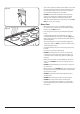
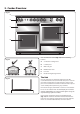
2. Cooker Overview ArtNo.025-0005 - Overview - 90 induction - 2 button clock & GO grill Fig. 2.1 A B C E D F Your 110 induction cooker (Fig. 2.1) has the following features: Fig. 2.2 A. 5 induction cooking zones B. Control panel C. Glide-out grill D. Multifunction oven E. Fan oven F. Bread Proving/Storage Drawer The Hob Fig. 2.3 Use only pans that are suitable for induction hobs. We recommend stainless steel, enamelled steel pans or cast iron pans with enamelled bases.
The very best pans have bases that are very slightly curved up when cold (Fig. 2.3). If you hold a ruler across the bottom you will see a small gap in the middle. When they heat up the metal expands and lies flat on the cooking surface. Fig. 2.4 Max: 1.85 kW Boost: 2.5 kW Max: 1.85 kW Boost: 3.0 kW Max: 1.85 kW Boost: 2.5 kW Zone 1 Zone 3 Zone 5 Make sure that the base of the pan is clean and dry to prevent any residue burning onto the hob panel. This also helps prevent scratches and deposits.
Residual Heat Indicator, H Power Level Auomatic Heat-up Time at 100% (min:sec) 1 0:48 2 2:24 3 3:50 4 5:12 5 6:48 Automatic Heat-up, A 6 2:00 7 2:48 8 3:36 This function is available on all of the cooking zones. It allows rapid heating up of the element to bring the selected cooking zone up to temperature. Once the zone is at the required cooking temperature the power level will reduce automatically to the preset level.
Low Temperature Setting, L1/L2 Each cooking area is equipped with 2 low temperature settings: • • Maximum Operating Time Power Level This function should only be used when heating nn from cold L1 will maintain a temperature of about 40 °C – ideal for gently melting butter or chocolate. L2 will maintain a temperature of about 90 °C – ideal for simmering (bring the pan to the boil and then select L2 to keep soups, sauces, stews, etc at an optimal simmer).
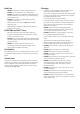
The Grill / Glide-out Grill Fig. 2.9 Open the door and pull the grill pan carriage forward using the handle (Fig. 2.9). The grill has two elements that allow either the whole area of the pan to be heated or just the right-hand half. Adjust the heat to suit by turning the knob. To heat the whole grill, turn the knob clockwise (Fig. 2.10). To heat the right-hand half, turn the knob counter-clockwise. The neon indicator light by the grill control will come on.
Bread Proving Drawer Fig. 2.12 The Bread Proving Drawer is found on the right at the base of the cooker (Fig. 2.12). Within the Bread Proving Drawer there are slots in the base to allow warmed air to flow through into the drawer from the element underneath. The Bread Proving Drawer temperature is ideal for proving all sorts of yeast dough from sweet to savoury, gluten free to sourdough, dough made from fresh yeast and dried, bread mixes and recipes from the Rangemaster Good Housekeeping Cookery book.
Function Use The Ovens Defrost To thaw small items in the oven without heat Fan oven A full cooking function, even heat throughout, great for baking The clock must be set to the time of day before the programmable oven will work. See the following section on ‘The Clock’ for instructions on setting the time of day.
Operating the Ovens Fig. 2.14 Multifunction Ovens The multifunction oven has two controls: a function selector and a temperature setting knob (Fig. 2.14). Turn the function selector control to a cooking function. Turn the oven temperature knob to the temperature required (Fig. 2.15). The oven indicator light will glow until the oven has reached the temperature you selected (Fig. 2.16). It will then cycle on and off during cooking.
This function operates the fan to circulate cold air only. Make sure the temperature control is at 0°C and that no heat is applied. This enables small items such as desserts, cream cakes and pieces of meat, fish and poultry to be defrosted. Fan Assisted Oven This function operates the fan, circulating air heated by the elements at the top and the base of the oven.
Using the Clock Fig. 2.18 You can use the clock to turn the left-hand oven on and off. Note: When using the timer functions, first set the clock as required before setting the oven temperature. The oven can be switched on when the cook symbol [ ] is displayed. Setting the Clock 1. The LCD clock is shown in (Fig. 2.18). Once the cooker is connected and switched on, the display flashes (00.00 ) and the time starts from (00.00 ). 2.
To Start and Then Stop the Left-hand Oven Set the left-hand oven to automatically start and stop using a combination of the ‘cook period’ and ‘stop time’. Fig. 2.24 You cannot set a start time directly – this is set automatically by a combination of the ‘cook period’ and ‘stop time’. ArtNo.306-0001 - 3-button clock 1. Press the mode [M] button until the display flashes (dur) (Fig. 2.24). Then set the ‘cook period’ using the [+] or [-] buttons. 2.
Accessories Fig. 2.29 Oven Shelves The oven shelves (Fig. 2.29) are retained when pulled forward but can be easily removed and refitted. Pull the shelf forward until the back of the shelf is stopped by the shelf stop bumps in the oven sides (Fig. 2.30). Lift up the front of the shelf so the back of the shelf will pass under the shelf stop and then pull the shelf forward (Fig. 2.31).
Bread Proving Drawer/Storage Fig. 2.36 The bottom drawer is for storing oven trays and other cooking utensils. ArtNo.340-0002 110 removing the drawer It can get very warm, so do not store anything in it that may melt or catch fire. Never store flammable materials in the drawer. This includes paper, plastic and cloth items, such as cookbooks, plastic ware and towels, as well as flammable liquids. Do not store explosives, such as aerosol cans, on or near the appliance.
3. Cooking Tips Hints on Using Your Induction Cooker General Oven Tips If you have not used an induction cooker before please be aware of the following: The wire shelves should always be pushed firmly to the back of the oven. • Baking trays with food cooking on them should be placed level with the front edge of the oven’s wire shelves. Other containers should be placed centrally. Keep all trays and containers away from the back of the oven, as overbrowning of the food may occur.
4. Cooking Table DocNo.031-0004 - Cooking table - electric & fan single cavity The oven control settings and cooking times given in the table below are intended to be used AS A GUIDE ONLY. Individual tastes may require the temperature to be altered to provide a preferred result. Food is cooked at lower temperature in a fan oven than in a conventional oven. When using recipes, reduce the fan oven temperature by 10 °C and the cooking time by 5-10 minutes.
5. Cleaning Your Cooker Isolate the electricity supply before carrying out any major cleaning. Allow the cooker to cool. Fig. 5.1 All parts of the cooker can be cleaned with hot soapy water. Take care that no surplus water seeps into the appliance. Remember to switch the electricity supply back on and reset the clock before reusing the cooker. Hob Daily Care First of all make sure that all heat indicator lights are off and that the cooking surface is cool.
Grills Fig. 5.2 The grill pan and trivet should be washed in hot soapy water. Alternatively, the grill pan can be washed in a dishwasher. After grilling meats or any foods that soil, leave to soak for a few minutes immediately after use. Stubborn particles may be removed from the trivet using a nylon brush. Removing the Glide-out Grill Pan The glide-out grill pan can be easily removed for cleaning as follows: Fig. 5.3 Remove the grill pan support frame by pulling the grill pan forward (Fig. 5.2).
Control Panel and Doors Fig. 5.7 Avoid using any abrasive cleaners, including cream cleaners. For best results, use a liquid detergent. The same cleaner can also be used on the doors. Alternatively, use a soft cloth wrung out in clean hot soapy water. You can use the same method for cleaning the control panel and knobs. After cleaning, polish with a dry cloth. Glass Fronted Door Panels (some models) ArtNo.
Cleaning Table Cleaners listed (Table 5-1) are available from supermarkets or electrical retailers as stated. For enamelled surfaces use a cleaner that is approved for use on vitreous enamel. Regular cleaning is recommended. For easier cleaning, wipe up any spillages immediately. Hotplate Part Finish Recommended Cleaning Method Hob top Enamel or stainless steel Hot soapy water, soft cloth. Any stubborn stains remove gently with a nylon scourer.
6. Troubleshooting DocNo.050-0001 - Troubleshooting - Induction GENERIC The cooling fan The induction hob incorporates a cooling fan. This cooling fan is active when either the grill or the oven(s) are on. Under certain conditions, the cooling fan may remain active when the grill or oven(s) are switched off. This is normal and the fan will switch off automatically. Interference with and repairs to the hob MUST NOT nn be carried out by unqualified persons.
Food is cooking too slowly, too quickly, or burning Cooking times may differ from your previous oven. Check that you are using the recommended temperatures and shelf positions – see the oven cooking guide. Then adjust the settings according to your own individual tastes. Fig. 6.1 ArtNo.324-0005 Oven light bulb The oven light is not working The bulb has probably blown. You can buy a replacement bulb (which is not covered under the guarantee) from most electrical stores.
The timed oven is not coming on when turned on manually Is the power on? Is the clock illuminated? If not, there may be something wrong with the power supply. Is the cooker supply on at the isolator switch? Has the time of day been set? Is the key symbol [] showing in the display to signify that the oven is locked? See the ‘Clock’ section of the instructions for more information on the key lock feature.
INSTALLATION Check the appliance is electrically safe when you have finished. 7. Installation Service and Spares Firstly, please complete the appliance details below and keep them safe for future reference – this information will enable us to accurately identify the particular appliance and help us to help you. Filling this in now will save time and inconvenience if you later have a problem with the appliance. It may also be of benefit to keep your purchase receipt with this leaflet.
INSTALLATION Check the appliance is electrically safe and gas sound when you have finished. Safety Requirements and Regulations Location of Cooker The cooker must be installed in a well-ventilated space, in accordance with the section entitled ‘Electrical Connection’. The cooker may be installed in a kitchen/kitchen diner but NOT in a room containing a bath or shower. nn This appliance is designed for domestic cooking only. Use for any other purpose could invalidate any warranty or liability claim.
INSTALLATION Check the appliance is electrically safe and gas sound when you have finished. Positioning the Cooker Fig. 7.1 75 mm min 650 mm min Fig. 7.1 and Fig. 7.2 shows the minimum recommended distance from the cooker to nearby surfaces. 75 mm min The cooker should not be placed on a base. The hotplate surround should be level with, or above, any adjacent work surface. A gap of 75 mm should be left between each side of the cooker ABOVE the hotplate level and any adjacent vertical surface.
INSTALLATION Check the appliance is electrically safe and gas sound when you have finished. Lowering the Two Rear Rollers Fig. 7.5 To adjust the height of the rear of the cooker, first fit a 13 mm spanner or socket wrench onto the hexagonal adjusting nut (Fig. 7.5). Rotate the nut – clockwise to raise – counterclockwise to lower. Make 10 complete (360°) turns clockwise. Make sure you lower BOTH REAR ROLLERS. Completing the Move Unfold the rear edge of the cardboard base tray.
INSTALLATION Check the appliance is electrically safe and gas sound when you have finished. Electrical Connection Fig. 7.8 This appliance must be installed by a qualified electrician to comply with the relevant regulations (AS/NZS 60335.2.6) and also the local electricity supply company requirements. Make sure that the mains characteristics (voltage, nominal, power, etc.) match the ratings indicated on the data plate affixed to the cooker. ArtNo.
INSTALLATION Check the appliance is electrically safe and gas sound when you have finished. Fixed Wiring Fig. 7.10 Disconnect from the mains supply. nn For connection to fixed wiring, i.e. flexible conduit, remove the electrical terminal cover on the back panel (Fig. 7.10). Fit the conduit box to the cooker using the two M5 screw fittings located at the top of the box. Remove the M4 screw from the base, and fix to the cooker, via the fitting through the back of the conduit box (Fig. 7.11).
INSTALLATION Check the appliance is electrically safe and gas sound when you have finished. Final Checks Fig. 7.14 Hob Check Check each cooking zone in turn. Be sure to use pans of the correct size and material. Grill Check Turn on the grill control and check that the grill heats up. Oven Check Set the clock as described earlier, and then turn on the ovens. Check the oven fans start to turn and that the ovens heat up. ArtNo.
WARNING – SERVICING TO BE CARRIED OUT ONLY BY AN AUTHORISED PERSON Disconnect from electricity before servicing. Check appliance is safe when you have finished. 8. Servicing Disconnect the cooker from the electricity supply nn before servicing, particularly before removing any 3. Controls 3.1 To Replace the Light Switch of the following: control panel, side panels, ceramic hob, or any of the electrical components or cover boxes. Disconnect from electricity supply. Remove the control panel (see 1.1).
WARNING – SERVICING TO BE CARRIED OUT ONLY BY AN AUTHORISED PERSON Disconnect from electricity before servicing. Check appliance is safe when you have finished. 4. Grill 4.1 To Replace the Grill Controller Disconnect from electricity supply. Lift up the hob and remove the control panel (see 1.1 and 2.1). Disconnect the wiring from the controller. Remove the two screws holding the controller to the mounting panel. Fit the new controller and reassemble in reverse order. Check for correct operation. 4.
WARNING – SERVICING TO BE CARRIED OUT ONLY BY AN AUTHORISED PERSON Disconnect from electricity before servicing. Check appliance is safe when you have finished. 5.3 To Remove an Oven Inner Back Fig. 8.1 Disconnect from electricity supply. Open the door and remove the shelves. Remove the screws and washers securing the inner back to the back of the oven (Fig. 8.1). Carefully lift away the inner back. Reassemble in reverse order making sure that the screws and washers are fully tightened. 5.
WARNING – SERVICING TO BE CARRIED OUT ONLY BY AN AUTHORISED PERSON Disconnect from electricity before servicing. Check appliance is safe when you have finished. Fig. 8.3 6. Doors Fig. 8.4 6.1 To Remove the Grill Door 2 1 ArtNo.320-0001 Door hinges ArtNo.320-0001 Door hinges Fig. 8.5 ArtNo.320-0006 Oven door hinge adjustment 1 Effect of hinge adjustment – exagerrated for clarity Fig. 8.6 Remove the left-hand side panel (see 1.2). Remove the control panel (see 1.1).
WARNING – SERVICING TO BE CARRIED OUT ONLY BY AN AUTHORISED PERSON Disconnect from electricity before servicing. Check appliance is safe when you have finished. 6.6 To Adjust the Main Oven Door Catch Keep Fig. 8.10 Open the oven door, and slacken off the locknut at the base of the keep (Fig. 8.9). Screw in or out as required until the required fit is obtained. Retighten the locking nut. 6.7 To Replace an Oven Door Seal Open the oven door.
9. Circuit Diagram Hob E 5 4 INDUCTION UNIT 3 2 1 HOB DISPLAY w/br w/br g/y b b Earth N(6) On Terminal Block N(5) On Terminal Block br br L(2) L(3) On Terminal Block 1 INTERFACE 2 BOARD 5 3 4 w/br w/br 1 2 w/br 5 3 4 Key The connections shown in the circuit diagram are for single-phase. The ratings are for 230 V 50 Hz.
Oven br r J b r b b r v w w br w C bk bk B1 J B2 b r B3 B4 B5 B6 b b b b I b B2 w 4 P4 3 P3 2 1 P2 P1 or bk bk b P7 P6 g B7 bk P8 7 v 5 y b 8 6 r br br Clock /Timer b b A1 v y b v br w I v r v bk r v v r 2 P2 1 P1 br y br w P5 bk y v M2 b r v br J b J D2 1 or 4 r P1 w br D3 or bk 2 r RH Oven v INDUCTION HOB 1 P2 P095199 A3 A4 br 2 2 v r H2 bk D1 W3 y v y Grill b P028728 bk 1 b r y M3 LH Oven y
10. Technical Data INSTALLER: Please leave these instructions with the user. DATA BADGE LOCATION: Cooker back, serial number repeater badge below the oven door opening. COUNTRY OF DESTINATION: Australia. Connections Electric 230 / 400 V ~ 50 Hz 3N Dimensions Model NEXUS 110 Induction Overall height maximum 930 mm minimum 905 mm Overall width 1100 mm Overall depth 608 mm excluding handles, 648 mm including handles Minimum height above the hotplate Hotplate Ratings 650 mm Max: 1.85 kW Boost: 2.
Hotplate Efficiency Brand Falcon Model Identification Nexus Size 110 Type Induction Type of Hob Induction Number of electric zones 5 Zone 1 - Ø cm 18.5 Heating Technology Energy Consumption (ECElectric cooking) - Wh/kg 172 Zone 2 - Ø cm 15.5 Heating Technology Energy Consumption (ECElectric cooking) - Wh/kg 180 Zone 3 - Ø cm 18.5 Heating Technology Energy Consumption (ECElectric cooking) - Wh/kg 172 Zone 4 - Ø cm 15.
Oven Data Brand Falcon Model identification Nexus Type of oven Electric Mass kg 130 Number of cavities 2 Left-hand Efficiency Fuel type Electric Cavity type Multifunction Power - conventional 2.2 Power - forced air convection 2.5 Volume Litres 73 Energy consumption (electricity) - conventional kWh / cycle 1.08 Energy consumption (electricity) - forced air convection kWh / cycle 0.91 Energy efficiency index - conventional 126.
Clarence Street, Royal Leamington Spa, Warwickshire, CV31 2AD, England. Tel: +44 (0) 1926 457400 Fax: +44 (0) 1926 450526 E-mail: consumers@falconappliances.co.