
User's Manual

42
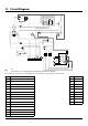
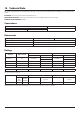
11. Circuit Diagram
ArtNo.080-0002 Classic 90 circuit diagram
Key
Code Colour
b Blue
br Brown
bk Black
or Orange
r Red
v Violet
w White
y Yellow
g/y Green/yellow
gr Grey
Code Description
A1 Right-hand oven thermostat
A2 Right-hand oven control switch
B Right-hand oven neon
C Clock
D Left-hand oven thermostat
E Oven light switch
F Ignition switch
G Right-hand oven fan
H Right-hand oven element
I Oven light bulb
J Spark generator
K Solenoid assembly
L Flame safeguard unit
Code Description
H1
H2
H3
FSI Neutral Links Harness
H4
Solenoid Harness Assembly
H5
Electrode and Sensor Wire Assembly
H6
Generator Harness (5 lead)
H7
HT Lead (Grill)
H8
Wire Assembly Cooling Fan live link
W1
NI
Wire Assembly (Earth Link)
NI
Wire Assembly (Earth x2)
NI
Earth Harness Assembly
Part No.
P064515
P064454
Fanned Oven Harness
Wire AssemblyCooling fan live link
90/100 FSI Main Harness P066474
P037863
P045153
P033723
P049242
P049292
P066475
P027672
P055374
P045165
NI
Not Illustrated
W2
Solenoid assembly
P033604
P055344 Wire Assembly fan link
W4
Neutral Wire Assembly P043965
H8
M
Thermal switch
N
Cooling Fan
C
LN
1
1a
1 2 3 4 5 6 E
11
N A
AN
Con6 Con7 JT1 JT2
brbr
or
b
bbr br
v
b
b
br
v
br
br
br
or
b
br
r
y
br
y
or
b
b
yb
br
b
b
b
or
or
2P2
1P1
1 2
y
y
r
or
b
v
b
b
br
c
c
b
b
br
br
b
b
br
br
Sensor
c
Spark
r
br
br
r
b
b
b
b
r
r
br
br
A1
A2
B
D
E
F
G
H
I
J
K
L
M
N
Code Description
A1
Right-hand oven thermostat
A2
Right-hand oven control switch
B
Right-hand oven neon
C
Clock
D
Left-hand oven thermostat
E
Oven light switch
F
Ignition switch
G
Right-hand oven fan
H
Right-hand oven element
I
Oven light bulb
J
Spark generator
K
Solenoid assembly
L
Flame safeguard unit
M
Cooling fan
N
Thermal switch
Key
The connections shown in the circuit diagram are for single-phase. The ratings are for 230 V 50 Hz.
Code Colour
b
Blue
br
Brown
bk
Black
or
Orange
r
Red
v
Violet
w
White
y
Yellow
g/y
Green/yellow
gr
Grey